TB67H420FTG motor driver not outputting to motor -Arduino

I am very confused on this.

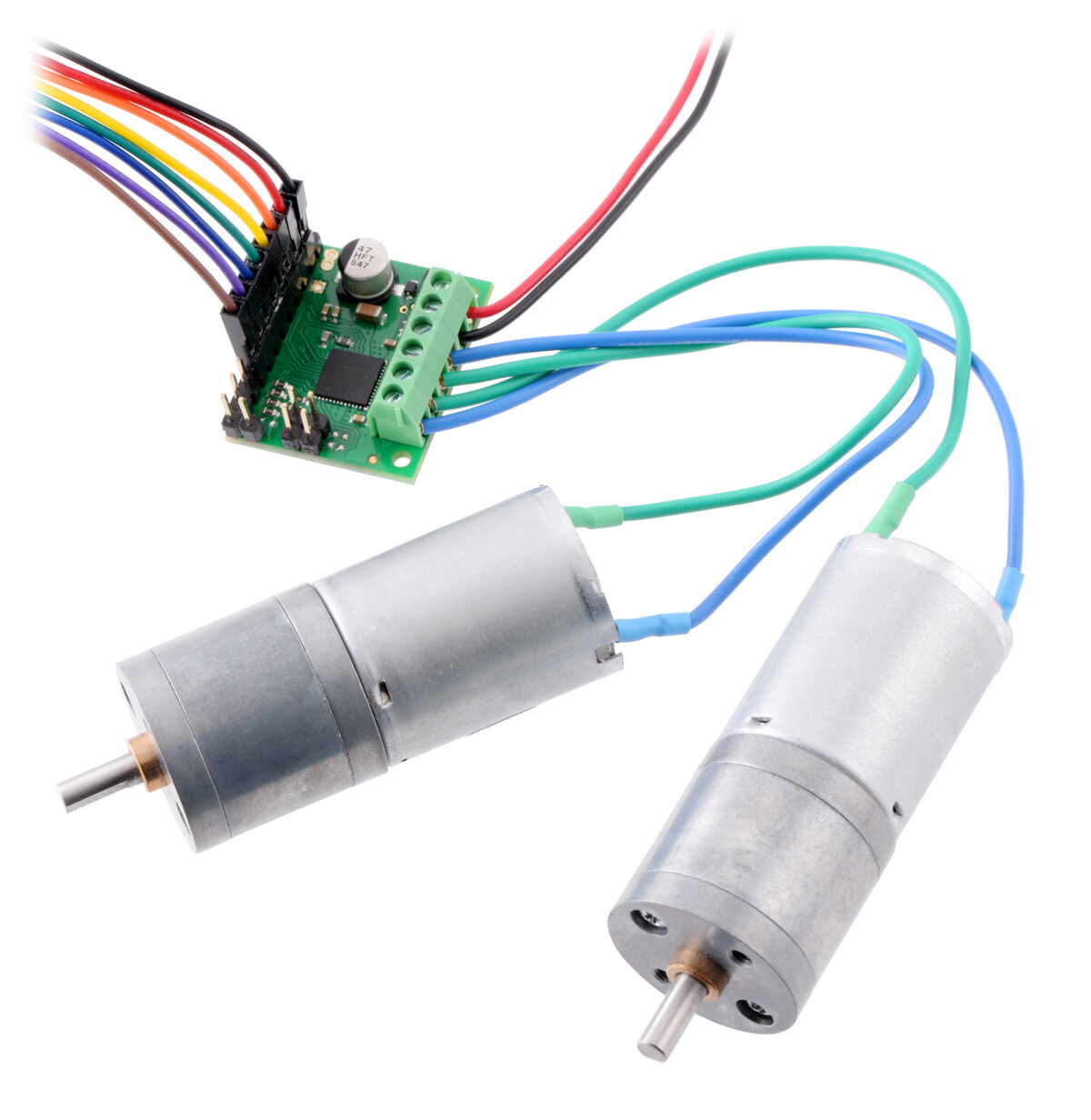
I’m using this motor: DC 12v Motor

This is the motor driver: TB67H420FTG

I know the motor works. I’m using an Arduino Nano 33 IoT, and I know it works. I can read encoder values from the motor and when I physically power the motor, it powers up and the encoder value is updated like you’d expect. The problem arises when I try to have the driver send power to the motor.

The code compiles file, no errors. Here’s my code:

#include "thingProperties.h"

#define ENCA 2
#define ENCB 3
#define PWM 5
#define IN1 7
#define IN2 6

int pos = 0;

void setup() {
  // Initialize serial and wait for port to open:
  Serial.begin(9600);
  pinMode(LED_BUILTIN, OUTPUT);
  // This delay gives the chance to wait for a Serial Monitor without blocking if none is found
  delay(1000);
  pinMode(ENCA, INPUT);
  pinMode(ENCB, INPUT);
  attachInterrupt(digitalPinToInterrupt(ENCA), readEncoder, RISING);
  // Defined in thingProperties.h
  initProperties();

  // Connect to Arduino IoT Cloud
  ArduinoCloud.begin(ArduinoIoTPreferredConnection);

  /*
     The following function allows you to obtain more information
     related to the state of network and IoT Cloud connection and errors
     the higher number the more granular information you’ll get.
     The default is 0 (only errors).
     Maximum is 4
  */
  setDebugMessageLevel(2);
  ArduinoCloud.printDebugInfo();
}


void loop() {
  ArduinoCloud.update();
  
  setMotor(1,40,PWM,IN1,IN2);
  delay(200);
  Serial.println(pos);
  Serial.println("TEST1");
  setMotor(-1,40,PWM,IN1,IN2);
  delay(200);
  Serial.println(pos);
  Serial.println("TEST2");
  setMotor(0,40,PWM,IN1,IN2);
  delay(200);
  Serial.println(pos);
  Serial.println("TEST3");
}

void setMotor(int dir, int pwmVal, int pwm, int in1, int in2){
  analogWrite(pwm,pwmVal);
  if(dir == 1){
    digitalWrite(in1,HIGH);
    digitalWrite(in2,LOW);
  }
  else if(dir == -1){
    digitalWrite(in1,LOW);
    digitalWrite(in2,HIGH);
  }
  else{
    digitalWrite(in1,LOW);
    digitalWrite(in2,LOW);
  }  
}

void readEncoder() {
  int b = digitalRead(ENCB);
  if (b > 0) {
    pos++;
  }
  else {
    pos--;
  }
}

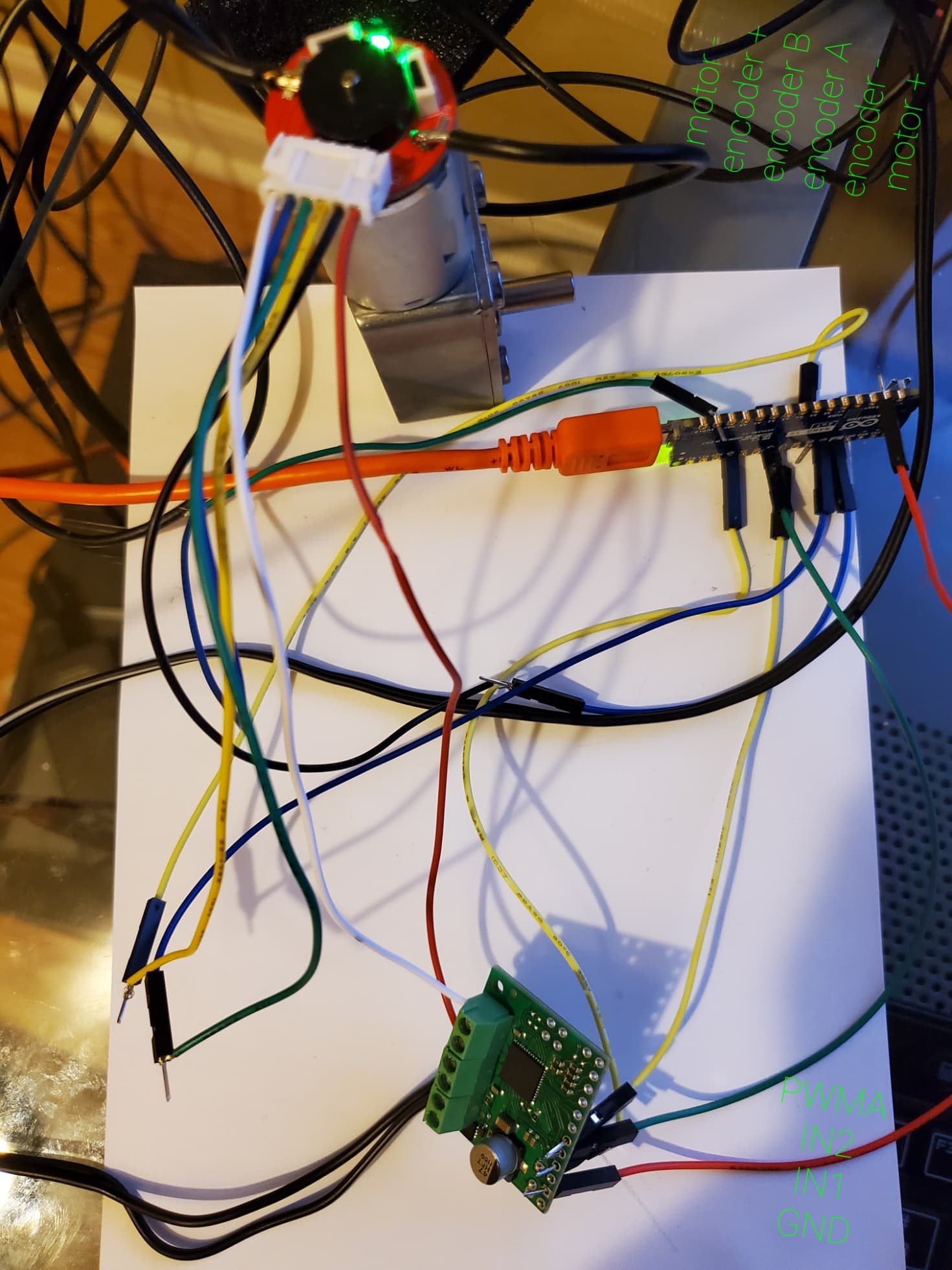
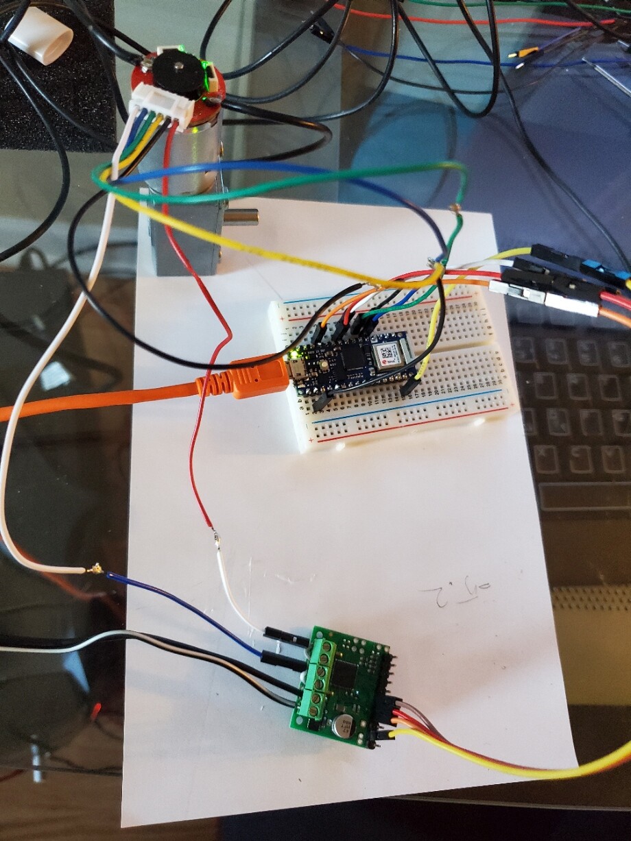
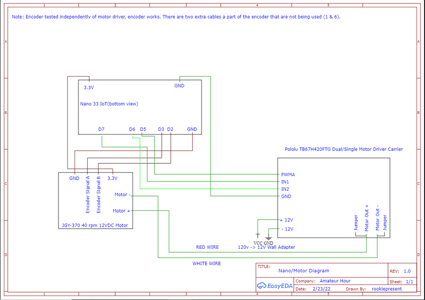
Here is a schematic of my set up:

So far, I’ve tried a range of values for the PWM. I’ve tried different delay times, ranging from 200 to 5000. I tried setting INPUT to INPUT_PULLUP. I know the power adapter I’m using is outputting about 14V. The Pololu board is brand new and this is my first time using a motor driver. There’s gotta be something simple I’m missing here, any help is appreciated. Thanks in advance.

Hi, is your setup getting sufficient power? What power supply are you using?

Hello.

I do not see anything obviously wrong with the way you’re describing your setup. As far as your code, have you tried setting the IN1 and IN2 pinMode() to OUTPUT? According to the Arduino documentation for digitalWrite(), if you do not set the pinMode() to OUTPUT, digitalWrite() will have enabled the internal pull-up resistor. Since the corresponding INA# and INB# pins on the TB67H420FTG are internally pulled-down, this would create a voltage divider, which could be causing the voltage to be too low for the driver to register.

If that does not help, could you post pictures of your setup that show all of your connections?

Brandon

I’m using a 120v to 12v wall adapter. I measured the voltage of the end when powered and was getting 14v, so I am sure the driver is getting power.

Thank you for the suggestions. I gave that a try, unfortunately didn’t change anything. Here is the code:


#include "thingProperties.h"

#define ENCA 2
#define ENCB 3
#define PWM 5
#define IN1 9
#define IN2 6

int pos = 0;

void setup() {
  // Initialize serial and wait for port to open:
  Serial.begin(9600);
 // pinMode(LED_BUILTIN, OUTPUT);
  // This delay gives the chance to wait for a Serial Monitor without blocking if none is found
  delay(100);
  pinMode(ENCA, INPUT);
  pinMode(ENCB, INPUT);
  pinMode(PWM, OUTPUT);
  pinMode(IN1, OUTPUT); 
  pinMode(IN2, OUTPUT);
  attachInterrupt(digitalPinToInterrupt(ENCA), readEncoder, RISING);
  // Defined in thingProperties.h
  initProperties();

  // Connect to Arduino IoT Cloud
  ArduinoCloud.begin(ArduinoIoTPreferredConnection);


  setDebugMessageLevel(2);
  ArduinoCloud.printDebugInfo();
}


void loop() {
  ArduinoCloud.update();

  
  setMotor(1,255,PWM,IN1,IN2);
  delay(5000);
  Serial.println(pos);
  //Serial.println("TEST1");
  setMotor(-1,255,PWM,IN1,IN2);
  delay(5000);
  Serial.println(pos);
  //Serial.println("TEST2");
  setMotor(0,255,PWM,IN1,IN2);
  delay(5000);
  Serial.println(pos);
  //Serial.println("TEST3");
}

void setMotor(int dir, int pwmVal, int pwm, int in1, int in2){
  analogWrite(pwm,pwmVal);
  if(dir == 1){
    digitalWrite(in1,HIGH);
    digitalWrite(in2,LOW);
  }
  else if(dir == -1){
    digitalWrite(in1,LOW);
    digitalWrite(in2,HIGH);
  }
  else{
    digitalWrite(in1,LOW);
    digitalWrite(in2,LOW);
  }  
}

void readEncoder() {
  int b = digitalRead(ENCB);
  if (b > 0) {
    pos++;
  }
  else {
    pos--;
  }
}

I did also move a pin to pin D9, so they were all on PWM capable pins, just in case. I did take a picture. It’s messy, but I labeled everything but the Arduino with green text. They’re oriented the same way as the wires, so the red motor + wire is the right most, the black wire next to it is encoder -, black wire, and so on. And the black/white and black wire going to the motor driver is the 120v to ~14v adapter. The black wires coming off the motor are other wires I soldered on to power the motor, but I’m not using them right now and they aren’t connected to anything. Orange cable powering my Arduino is plugged into USB on my PC.

Thank you for the additional information and pictures. It looks like you haven’t soldered any of your connections. You will need to solder them to ensure a good electrical connection, and when you’re done they should resemble the examples shown in the Adafruit Guide to Excellent Soldering (which is a great resource if you’re relatively new to soldering). I typically prefer using male or female header pins so it is easy to change connections with jumper wires.

Brandon

I went ahead and soldered some pins to the Nano and to the Pololu board. I also soldered the encoder wires to male pins. I tested the encoder first, with the breadboard, and encoder and motor work fine when I power it manually. When I connect the driver and run the same program, no change, it doesn’t power the motor at all. Here is a new picture of the setup, and the code I’m using after that:

/*
  Sketch generated by the Arduino IoT Cloud Thing "Coop Control"
  https://create.arduino.cc/cloud/things/4217e43c-751f-4f0f-9f0c-3b0e77887e97

  Arduino IoT Cloud Variables description

  The following variables are automatically generated and updated when changes are made to the Thing

  CloudSchedule schedule_variable;
  bool door_Motor;

  Variables which are marked as READ/WRITE in the Cloud Thing will also have functions
  which are called when their values are changed from the Dashboard.
  These functions are generated with the Thing and added at the end of this sketch.
*/

#include "thingProperties.h"

#define ENCA 2
#define ENCB 3
#define PWM 5
#define IN2 6
#define IN1 7

int pos = 0;

void setup() {
  // Initialize serial and wait for port to open:
  Serial.begin(9600);
 // pinMode(LED_BUILTIN, OUTPUT);
  // This delay gives the chance to wait for a Serial Monitor without blocking if none is found
  delay(100);
  pinMode(ENCA, INPUT_PULLUP);
  pinMode(ENCB, INPUT_PULLUP);
  pinMode(PWM, OUTPUT);
  pinMode(IN1, OUTPUT); 
  pinMode(IN2, OUTPUT);
  attachInterrupt(digitalPinToInterrupt(ENCA), readEncoder, RISING);
  // Defined in thingProperties.h
  initProperties();

  digitalWrite(IN1, HIGH);
  analogWrite(PWM, 100);
  delay(5000);

  // Connect to Arduino IoT Cloud
  ArduinoCloud.begin(ArduinoIoTPreferredConnection);

  setDebugMessageLevel(2);
  ArduinoCloud.printDebugInfo();
}


void loop() {
  ArduinoCloud.update();
 
  setMotor(1,40,PWM,IN1,IN2);
  delay(1000);
  Serial.println(pos);
  //Serial.println("TEST1");
  setMotor(-1,40,PWM,IN1,IN2);
  delay(1000);
  Serial.println(pos);
  //Serial.println("TEST2");
  setMotor(0,40,PWM,IN1,IN2);
  delay(1000);
  Serial.println(pos);
  //Serial.println("TEST3");
}

void setMotor(int dir, int pwmVal, int pwm, int in1, int in2){
  analogWrite(pwm,pwmVal);
  if(dir == 1){
    digitalWrite(in1,HIGH);
    digitalWrite(in2,LOW);
    Serial.println("dir is 1");
  }
  else if(dir == -1){
    digitalWrite(in1,LOW);
    digitalWrite(in2,HIGH);
    Serial.println("dir is -1");
  }
  else{
    digitalWrite(in1,LOW);
    digitalWrite(in2,LOW);
    Serial.println("dir is else");
  }  
}

void readEncoder() {
  int b = digitalRead(ENCB);
  if (b > 0) {
    pos++;
  }
  else {
    pos--;
  }
}

I tried to turn the motor on from the start, with the code above. The motor does not turn on, and the serial reads this:

***** Arduino IoT Cloud - configuration info *****
Device ID: 15b23667-95d4-4206-9016-1dd3a1ec8c5c
MQTT Broker: mqtts-sa.iot.arduino.cc:8883
WiFi.status(): 0
Current WiFi Firmware: 1.4.8
dir is 1
0
dir is -1
0
dir is else
0
Connected to "WIFI"
dir is 1
0dir is -1
0
dir is else
0
dir is 1
0
dir is -1
0
dir is else
0
dir is 1
0
dir is -1
0
dir is else
0
dir is 1
0
dir is -1
0
dir is else
0
dir is 1
0
dir is -1
0
dir is else
0
dir is 1
0
dir is -1
0
dir is else
0
dir is 1
0
dir is -1
0
dir is else
0
dir is 1
0
dir is -1
0

0
Connected to Arduino IoT Cloud
Thing ID: 42...
dir is 1
0
dir is -1
0
dir is else
0
dir is 1
0
dir is -1
0
dir is else
0
dir is 1
0
dir is -1
0
dir is else
0
dir is 1
0
dir is -1
0
dir is else
0
dir is 1
0
dir is -1
0
dir is else
0
dir is 1
0
dir is -1
0
dir is else
0
dir is 1
0
dir is -1
0
dir is else
0
dir is 1
0
dir is -1
0
dir is else
0
dir is 1
0
dir is -1
0
dir is else
0
dir is 1
0dir is -1
0
dir is else
0
dir is 1
0
dir is -1
0
dir is else
0
dir is 1
0
dir is -1
0
dir is else
0
dir is 1
0
dir is -1
0
dir is else
0
dir is 1
0
dir is -1
0
dir is else
0
dir is 1
0
dir is -1


By default, the TB67H420FTG runs in dual-channel mode and drives two motors independently, but it looks like you are trying to use it in a paralleled single-channel mode. To run the driver in single-channel mode, you need to connect the HBMODE pin to a logic high voltage, which it looks like you have not done.

However, the driver should be able to handle more than enough current for your motor in dual-channel mode, so I suggest removing the jumpers you currently have between the motor output channels, and just connecting your motor wires to A- and A+ for now. So, your setup should essentially match the dual-channel mode picture on the driver’s product page, but without the connections for channel B:

If that does not work, can you post close-up pictures of both sides of your TB67H420FTG driver carrier?

Brandon

Switching to dual-channel mode worked! Thank you very much!