TB6612FNG Dual Motor Driver Carrier problem

I just received this and started testing. I used an Arduino Fio and just used VCC (3.3v) for all positive voltage to start with and used a sketch I found on the Arduino forum but changed the pins for the Fio. I started testing the A channel and the motor spun fine in one direction but not the other, so I tried changing the PWM values and submitting again a few times. After a few tries, it did not spin at all anymore. I changed the values back to what they had been before, but it still did not spin in either direction. I checked voltages going in and they are fine. I wired the motor directly to VCC and GND and it spins fine. I powered everything off, waited and then back on. It doesn’t work anymore. It isn’t hot or anything; it just seems dead.

It went from working to not working with no changes to how it is wired, but here are pictures of it and code despite that.

white wires in upper right lead to little DC motor.

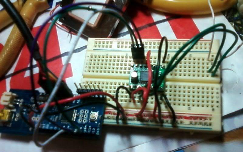
In preview, it appears to cut off part of the picture so here is the link:
http://i43.photobucket.com/albums/e396/arbarnhart/screen%20shots/TB6612FNG.jpg

Sketch below. Note that the pins for channel B were not connected. I planned to tst them after finishing with A.

//Configure these to fit your design...
//#define out_STBY 9
#define out_B_PWM 3
#define out_A_PWM 9
#define out_A_IN1 10
#define out_A_IN2 11
#define out_B_IN1 5
#define out_B_IN2 6
#define motor_A 0
#define motor_B 1
#define motor_AB 2

void setup()
{
  //pinMode(out_STBY,OUTPUT);
  pinMode(out_A_PWM,OUTPUT);
  pinMode(out_A_IN1,OUTPUT);
  pinMode(out_A_IN2,OUTPUT);
  pinMode(out_B_PWM,OUTPUT);
  pinMode(out_B_IN1,OUTPUT);
  pinMode(out_B_IN2,OUTPUT);
  
 // motor_standby(false);
  motor_speed2(motor_A,-100);
  motor_speed2(motor_B,-100);
  delay(2000);
  for (int i=-100; i<100; i++) {
    motor_speed2(motor_A,i);
    motor_speed2(motor_B,i);
    delay(50);
  }
  delay(2000);
//  motor_standby(true);
}

void loop()
{

}

void motor_speed2(boolean motor, char speed) { //speed from -100 to 100
  byte PWMvalue=0;
  PWMvalue = map(abs(speed),0,100,50,255); //anything below 50 is very weak
  if (speed > 0)
    motor_speed(motor,0,PWMvalue);
  else if (speed < 0)
    motor_speed(motor,1,PWMvalue);
  else {
    motor_coast(motor);
  }
}
void motor_speed(boolean motor, boolean direction, byte speed) { //speed from 0 to 255
  if (motor == motor_A) {
    if (direction == 0) {
      digitalWrite(out_A_IN1,HIGH);
      digitalWrite(out_A_IN2,LOW);
    } else {
      digitalWrite(out_A_IN1,LOW);
      digitalWrite(out_A_IN2,HIGH);
    }
    analogWrite(out_A_PWM,speed);
  } else {
    if (direction == 0) {
      digitalWrite(out_B_IN1,HIGH);
      digitalWrite(out_B_IN2,LOW);
    } else {
      digitalWrite(out_B_IN1,LOW);
      digitalWrite(out_B_IN2,HIGH);
    }
    analogWrite(out_B_PWM,speed);
  }
}
void motor_brake(boolean motor) {
  if (motor == motor_A) {
    digitalWrite(out_A_IN1,HIGH);
    digitalWrite(out_A_IN2,HIGH);
  } else {
    digitalWrite(out_B_IN1,HIGH);
    digitalWrite(out_B_IN2,HIGH);
  }
}
void motor_coast(boolean motor) {
  if (motor == motor_A) {
    digitalWrite(out_A_IN1,LOW);
    digitalWrite(out_A_IN2,LOW);
    digitalWrite(out_A_PWM,HIGH);
  } else {
    digitalWrite(out_B_IN1,LOW);
    digitalWrite(out_B_IN2,LOW);
    digitalWrite(out_B_PWM,HIGH);
  }
}

Hello,

If you want anyone to be able to help you, you will have to provide more information. What are the specs of your motor? What kind of power supply are you using? Can you show us a diagram of your setup and photos of your connections? Can you post the code you are running on your Arduino?

- Kevin

EDIT: It looks like you updated your post while I was writing this - I will take a look.

One thing that stands out to me from your picture is that you are taking your motor voltage (VMOT) from the Fio’s 3.3 V regulated output. It is unlikely that this is providing adequate current for your motor (unless it is very tiny). You should try to connect VMOT to a separate power supply such as a bench supply or a battery. Also, it would still be helpful for you to provide some specs on the particular motor you are using.

I have not taken a close look at your code yet, but I formatted it to make it more readable - in the future you can do this by putting it in between [code][/code] tags.

The motor is from a 3v fan. Slightly overdriven at 3.3, but not enough to worry about.

But as I said before editing, it worked in one direction but not the other, then I tried changing PWM values and it quit working and would not work at all after that. Since I said that even before editing, it is very likely that 3.3v supplies enough power for the motor.

My edits added the picture and code to support what I said.

Another edit, sorry - I forgot about your power supply question. The connector in the picture is an FTDI connector. They are pretty common in microcontrollers. I will dig up some info if you are unfamiliar with them, though my patience is pretty short with explaining an obviously bad $9 part.

Hello.

I’m sorry to hear you’re having trouble with the motor driver, and I understand if you think not it’s worth it to spend time debugging a $9 part, but it’s very unlikely that the part is defective, so it would be beneficial for you to take some time to try to figure out what you’re doing wrong, especially since it seems like you might be new to motor control. Instead of using a random (and overly complicated sketch) you found somewhere, I recommend simplifying things greatly:

  1. Disconnect the motor.
  2. Connect the PWM line to VCC.
  3. Connect one of the direction inputs to VCC and the other to ground
  4. Use a multimeter to measure the voltage on the driver outputs
  5. Try this with both motor channels.

Also, the FTDI’s regulator can only provide a few tens of milliamps and is definitely not suitable for driving a motor. Note that while I expect the motor driver to work with VMOT at 3.3V, the minimum recommended voltage for VMOT in the driver datasheet is 4.5 V, so if you continue to have trouble, you should check to see if things get better when you raise VMOT.

- Ben

Random? A sketch that uses the same microcontroller I do to drive motors with this board and has functions to go forward or backward at different speeds, stop or coast on either motor is not random. I did a lot of searching to find a suitable sketch. The demo it performs in the start up code may be somewhat random, but it is a good indicator of whether or not things are hooked up right. No, I am not new to motor controllers. This is to replace a motor shield, which requires a “full size” Arduino with headers and I need this to fit in a smaller space.

If your board worked, I would consider the code a decent sample. It is used in a few Arduino projects that do exactly what I am trying to do, though they were using the SFE variant of the board.

I tried testing your suggestion with 5v instead of 3.3 to all the positive inputs. I checked that voltage on the meter and got 5.37. I connected that voltage to VCC, VMOT, PWMA, AIN1 and STBY, then connected GND to the other 3 corners and AIN2. Between AO1 and AO2 I get 0.0. I swapped AIN1 an AIN2. Still 0. Both high - 0. Both low - 0. I fail to see the point in trying channel B.

The point of trying channel B is that, if it works with the same connections you made to channel A, then we can be sure that channel A on the chip is defective. Otherwise, it is still possible that something else in your setup is causing the problem.

There are potentially two issues with the power supply for your motor: the voltage and the current. I am not so sure that the voltage is an issue, but as both Ben and I have mentioned, the regulator on the Fio probably cannot provide enough current to run your motor well (unlike a standard Arduino + motor shield). You mentioned that you tried it with a 5 V supply, and that is a good start, but what are you using to produce the 5 V? If it is another small regulator, it may have the same problem of not being able to provide enough current.

- Kevin

I used a 300 ma wall wart to provide the 5.5v.

As I mentioned in my initial post, the motor I was testing I ran from VCC as a a test and it ran fine; reversed the leads and it ran the other way. It is a tiny motor I was only using to test the motor control before I tried running something with more juice and a bigger motor.

The test Ben had me run was pure electrical connectivity based and I confirmed voltage and ground on all leads. According to the data sheet, it should have produced voltage on output pins. It did not. I am done testing.

So what’s the next step? I did a hardware check following instructions from one of your techs (Ben) and the board failed the test. Do I pack it and send it back? Please send me the info on printing a label.

Hello,

If your board is actually damaged, it is worthwhile to try to figure out what caused it so that it does not happen to your next one. I was puzzled for a while about how you could have possibly damaged the board with such a weak power supply, but now I have a thought about that - take a look at this quote from the TB6612FNG datasheet:

Your program is designed to slow down the motor and then reverse its direction. While decelerating or reversing, the motor & driver can together act as a generator, sending current back in to your power supply. This current can be as high as the stall current of your motor, even if the motor was never stalled. On other boards, we have seen this cause voltage spikes of more than ten volts on the motor power supply, and that could easily have happened to you, especially since the “current sink capability” of your power supply is definitely quite small. Normally, if your motor supply spiked up to 13V, it would not be a problem, but since you were also using that as your logic supply, it could have overloaded the logic inputs of the chip, causing all kinds of damage.

This is yet another reason that small linear regulators are almost never suitable for driving motors. I highly recommend using a motor supply rated for the stall current of your motor and a separately regulated logic supply.

-Paul

There will be no next one. If I return it, it would be for credit and I would get something else. I have abandoned the idea of using the low end RC truck chassis I was planning to use it with and instead bought a higher end RC truck chassis with an ESC and servo that I will control with PWM. I have had good experience doing that on another project, but thought I might get by with a cheaper prototype for this one, but the hassle and frustration factor is just too high.

Should I put it in the trash or the mail?

BTW, my other recent purchase from you, a 5W 5V regulator, rocks! It is in use on a different project where I had too many components sucking up system power on an Arduino MEGA. My frustration is more with technology than Pololu, but you are a far easier target to aim at. That bit from the data sheet does make sense and when I consider that forward was working and then quit after I kept trying that sketch, I guess it is likely that caused it. That wasn’t my first reaction. The first thing I did was shake my head in disbelief and hook the little motor up to my meter and spin the shaft between my finger and thumb. I got voltage and it rises with speed.

I don’t like the answer, but thanks for getting me there…

Hello.

Thanks for the extra comments in your latest post; I am happy to hear that your experience with our products has not been entirely negative. Regarding your return question, our return policy (for some kind of credit or money back) is limited to unopened items. We might want some products back if it we thought they were likely to work fine or if they were a new design whose failure we wanted to study more, but in this case, we trust that your unit is damaged, and we don’t expect that there’s much to learn since this is a simple product that has been out for some time.

- Jan

This has been puzzling me for a while too. L298 and SN75440 designs are required to have external diodes to deal with back-EMF, and people seem to use physically large ones ( dfrobot.com/image/data/DFR0004/Layout.pdf ). The TB6612FNG like the L293D has internal diodes but the size disparity makes me wonder about on-die diodes. The sparkfun discussion on the SN75440 has the dry remark:

I’m abusing/wasting motor controllers a different way right now (uh, PC fans; doing a single high-side drive per channel through an RC filter, so I have my own problems and suspect I need to clamp at least once externally.) But for people using the H-bridge the right way, yet under somewhat abusive testing conditions, would external diodes be worthwhile, or as useful as racing stripes, or somehow harmful?

Hm. Should I stop using the 9v transistor battery as a test supply for small loads? (EDIT: yeah, in the FAQ that they probably won’t work for real motors, but it doesn’t say “don’t”.)

BTW, don’t feel compelled to say anything about my app; “I bet you’ll be ordering another controller shortly” is as fine response as any. If I expected a design service I’d pay for it. :slight_smile:

Hello,

I do not know why people continue to make new boards based on the L298 and SN754410, but if you are working with those chips, you should definitely be careful about all kinds of things.

The right way to do an H-bridge in most situations these days is with MOSFETs, and MOSFETs have built-in diodes that do exactly what you need when they are connected in an H-bridge configuration. They are probably good enough for most applications, but you do not have to guess - just look up the datasheets for the MOSFETs you are using and make sure that the body diode can handle the kinds of currents that you will be putting through it, and that the chip can dissipate the resulting power.

By the way, the problem I was referring to is not really related to the diodes at all. When you are trying to slow down a motor with deceleration, a large current builds up (as much as the stall current of the motor) in the motor coils and braking circuit during the brake phase of the PWM cycle, and that current is switched into your power supply during the on phase. The best defense against that is probably huge capacitors all over the place and having a regulator between your motor supply and your logic supply. A high PWM frequency should also make it better (the example in this thread used a very low frequency.)

Anyway, I do not know exactly what you are doing, but if you are PWMing an H-bridge, and if you will be decelerating a motor with a stall current of more than 1A or so, it would be informative to put a meter on your 9V battery and watch what the voltage does under different deceleration conditions.

-Paul

Just a followup…

While I do believe you may have figured out what killed the module, the more I think about it and discuss it with others, the more I think it is unacceptable for you to sell a product that is that frail. The spike had voltage that possibly went as high as 10 or 12, but the current was milliamps and probably well under 100 (likely under 20; this was a tiny motor; my meter can’t even detect it spinning on anything but volts). If there were some notes/warnings included with it suggesting any sort of protection instead of just specifying the pins as VOUT I might feel differently.

The code I ran that seems to be responsible is from the Arduino forum and lots of users have run it to test then adapted it for their use. But their TB6612FNG boards were red instead of green and they worked instead of dying.

Also…

and a high frequency and everything in between. The loop that goes up to 100 is using percent.

It sounds like you want things to magically be arbitrarily good. Electronic components can be very fragile, and it’s just pointless to get upset about a pin with an absolute maximum of 6V not taking 12V. What do you think is different about the Sparkfun version? Do you think it’s unacceptable for grocery stores to sell eggs?

I realize it’s frustrating when parts break, but please understand that we have sold literally thousands of each of these products (the motor driver carrier and RS-232 adapter), and you are in the extremely small minority of people having problems with it, and at least some of those problems could be due to easily identifiable abuses you inflicted on the parts.

- Jan

I expect to be able to exactly follow directions from examples of others using the same chips and have them work. I don’t think that is arbitrary. I was explaining the issue with the motor controller to an friend with an engineering background and he told me he doesn’t buy it for a minute. Even the Fio’s pitiful VCC would sink the voltage from this tiny motor. The Fio did not crash nor suffer any damage. The explanation about the motor driver has some basis even though it seems a stretch. Your explanation of the serial problem is laughably absurd.

You seem to be confusing “duty cycle” with “frequency”. For duty cycles under 100%, your program is using a fixed, low PWM frequency (approximately 490 Hz).

I assume the people whose boards worked also used proper power supplies (in my experience, very few people try using such a woefully underpowered regulator to drive motors). Did the instructions you followed say to use the 3.3V output of an FTDI chip as your power source? If not, it certainly isn’t fair to say you were following the instructions of others “exactly”.

The red-vs-green distinction isn’t really relevant since both the Sparkfun and Pololu boards are just simple carriers for the same TB6612FNG motor driver IC (you can compare the schematics for the two boards yourself); for all intents and purposes, you are basically just directly using Toshiba’s motor driver, and we really do think it’s a great IC. We use it in a number of our products, and problems with it are very rare (I don’t actually recall anyone else who’s ever contacted us about a TB6612 driver failure).

- Ben

There was someone else even in this thread. Out on the Arduino board, there are some stories of failure with no answers and the wiring seems right. Others post sucess. Some are using VCC to drive motors and usually are told that’s bad form even though it is working, but it doesn’t seem to be a consistent indicator of failure.

here is an example:
http://www.arduino.cc/cgi-bin/yabb2/YaBB.pl?num=1268513899

I don’t know why the person didn’t contact you.

Hello,

Nobody else in this thread said that their TB6612FNG broke, and the thread on the Arduino forum that you linked to specifically says there is nothing wrong with the motor driver.

How do you expect us to be able to control the directions that other people write up? If they make some mistake or are unclear in their write-up, you could damage your board.

-Paul