I just wanted to ask if there is any way that two 1600 mA micro metal gearmotors hooked in series could blow something in the TB6612FNG Dual Motor Driver Carrier, both outputs being hooked together. I was doing a pushing test with my 4wd mini sumo, when suddenly one half of the robot lost mobility because something happened to the TB6612FNG controller controlling those two motors. I checked the inputs, and there was nothing wrong there, supply voltage was good, and everything looked fine except the TB6612FNG just wasn’t giving out current to the motors.
The only interesting thing about my wiring was that since I’m controlling 4 1600 mA motors with two TB6612FNG Dual Motor Driver Carriers, I figured that since the motors on each side of the robot must work in tandem, I simplified the wiring by connecting the AIN1 with BIN1, AIN2 with BIN2, and did the same for the outputs. Everything had been working fine for the last week or so, until now. However it’s worth noting that this has been the most pressure I’ve put on my motors; until now I’ve been avoiding letting the motors stall too much. This looks like a problem internally on the board itself, so I don’t have any idea where to start looking for solutions. I have a backup carrier I can plug back in, but I don’t want to do so if there’s a possibility of something like this happening again.
Some other things:
I didn’t notice any heat coming from the chip or the capacitor. However it’s possible that one of these did overheat, but the heat dissipated rapidly.
I’ve been noticing that if I stall one motor in a series, the other will accelerate. If I release the stalled motor, the current will average back out between the two. However, after a certain point, all the current goes to one motor, and the other doesn’t move again. I’m a little bit of a novice with motor control, I’ve used mostly servos in previous applications, but I know that motors can create current moving in the wrong direction, damaging controllers. The TB6612FNG Dual Motor Driver Carrier has a reverse current protection, but is there a certain limit to how much it can resist? Reverse current protection is created by diodes, correct? Is there any absolute maximum rating?
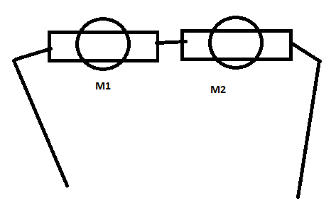
Can you tell us more about your setup? What is your power supply? Can you post a picture of your setup? Can you draw a wiring diagram of your setup in a drawing program (e.g. MSPaint)? Feel free to use pictures from our website. Are you using some HP micro metal gearmotors from us? Which gear ratio? When you were doing your pushing test, were you pushing the robot or was it pushing something else?
Yes, the TB6612FNG has flyback diodes because it uses MOSFETs for the H-bridge legs. There are all sorts of absolute ratings; with more information about your setup, we can have a better idea of what might have gotten violated.
Thanks for the wiring diagram. We do not recommend paralleling the outputs of a the Baby Orangutan’s motor driver because you cannot also parallel the inputs. Is the Baby Orangutan side the side that broke? Also, why have you left PWMA and PWMB separated on the the carrier connections? Can you answer my other questions? Can you confirm that this diagram represents how you have your motors wired?
Power supply - 2 6v battery packs (4 AA) hooked in parallel.
I use HP 50:1 micro metal gear motors
When I did my pushing test, I took a digital scale placed on its side, and made the robot push the surface of the scale.
Your diagram is how I hooked the motors. I realize that the inputs to the Baby-O can’t be paralleled, but that wasn’t the issue in this case. In fact, it was the TB6612FNG Dual Motor Driver Carrier board side that failed.
About the separate pwm connections on the carrier - yes I realize that’s a discrepany.
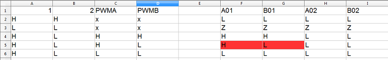
Sorry for the delay in responding, I was looking into a detail about the TB6612FNG. I started writing the truth table from your wiring diagram, and it quickly became clear that it is very easy for power to become shorted to ground through the chip. Here is the partial truth table below:
If your input signals are different and your PWM signals are different, even for a short time, you will be dumping a whole bunch of power through the chip (perhaps every PWM cycle). It might have heated up quickly enough to bypass the built-in thermal shutdown protection.
If you email us directly, referencing this forum thread, we might be able to get you a discount on some replacement drivers. If you try again, I recommend tying the PWM lines together so that they’re guaranteed to be in sync.
Please also note that we generally do not recommend connecting batteries in parallel unless you know what you are doing and are very careful.
It was a simple forward driving test; so there wasn’t any room for unexpected violations in the truth table.
After some thought, is it possible for me to link my motors directly to the Baby-O without having any additional controller? Since they’re hooked in series, the motors consume twice as much voltage than an individual motor would, but draw the same current as one motor as well, right? Because of this, they don’t exceed the peak current limitations of the onboard motor driver.
There is still room for violations in a simple forward test. For example, setting the duty cycle of the timer outputs might not be completely synchronized.
You are correct about your reasoning about motors in series. However, driving motors in series tends to not be that great because when one motor gets more load, it responds with delivering less power, which is usually the opposite of what you want.
I don’t see anything inherently wrong with your code, though there could still be problems with shorted outputs driving to different voltages if the Baby Orangutan I/O lines are ever floating, such as might happen if it is unpowered or reset. If you would like me to help you debug this further, I would be interested in seeing a picture of your setup and a diagram of how your logic and motor power supplies are wired.
Before I get my hands dirty with showing the wiring diagrams and things, I’m going to plug in my backup driver I bought, and put the motors in parallel. If the problem comes up again I’ll post.
It’s ok to drive the pwm ports high, right?
By paralleling your motors, you have the potential of doubling the current draw compared to having them in series. The inputs pins on the TB6612FNG (including PWMA/B) can be driven to both logic high and logic low. I do not recommend using the backup driver until you correct the issue with the PWMA/B lines being controlled separately.
I don’t understand what you are asking. In my last post, my first sentence as referring to the motors connected to the outputs of the TB6612FNG. The other sentences are referring to inputs of the TB6612FNG. Please let me know if that does not answer your question.
Problem is resolved. Turns out it was a frayed wire that somehow got cut in the pushing test, probably because of the jerking movements. Thanks for your help anyways, and I’ve learned a surplus of information about the TB6612FNG simply by troubleshooting. Hopefully I’ll share my minisumo soon.


 At least they’re the last thing I want to investigate thoroughly.