I’m confused about what PWM signals the TB6612FNG needs to function. When I read the data sheet I get the impression that the forward/reverse/brake function of the driver is controlled by the state of the A/BIN1 and A/BIN2 input pins on the driver, while the speed of rotation is controlled by the PWM A/B pins respectively. So, you would only need digital signals to theA/BIN1 and A/BIN2 pins, with a PWM signal to PWM A/B pins. I’ve attached the table from the TB6612FNG data sheet that I am basing all my assumptions on for reference.
How come the documentation that is linked under resources for the TB6612FNG the the 3pi robot uses four separate PWM channels and why are they inverted?
From the data sheet, it looks like the PWM signal would induce rotation when high and a short break when low. I’m just trying to fully understand the theory before I start pugging away with programing. Thanks in advance!
The control scheme used on the 3pi is intended to minimize the number of I/O lines needed. It does not use the driver’s PWM input at all; rather this pin fixed high and PWMs are applied directly to the IN1 and IN2 pins. To drive “CW”, an inverted PWM is applied to IN2 while IN1 is held high. To drive “CCW”, an inverted PWM is applied to IN1 while IN2 is held high. This causes the driver to alternate between drive and short brake (which leads to better performance than alternating between drive and stop/coast). The reason for inverting the PWM is that a 0% duty cycle results in high, which produces 100% short brake when the other input is also high. A duty cycle of 100% results in low, which results in full speed CW or CCW when the other input held high.
Clever, so you are effectively achieving the same functionality using the IN1/2 (2 I/O) as you could have with constant signals to the N1/2 pins while letting the PWM signal switch the driver between “rotation” and “short break” (3 I/O). Thanks for the clarification!
I know this thread is over a year old but I have a related question and figured this was the best place. Rather than attaching both sides of each motor to a PWM pin, could you have saved two of your PWM pins (Timer2’s counter registers for example) by just attaching one side of each motor to PWM? I think the effect would be the same, you’d just have to inverse the interpretation of the PWM size when reversing, for example? Is this correct?
I am not sure what you mean when you say “attaching both sides of each motor to a PWM pin”, but your question makes it sound like you are wondering if you really need to supply PWM signals to the two IN pins for each channel. The main drawback with the alternative you are proposing (i.e. one PWM connected to one of the IN pins that you invert if you want to change direction) is that you will get asymmetric behavior: in one direction the driver will be alternating between drive and brake while in the other it will be alternating between drive and coast. A better way to reduce the number of PWM control signals needed would be to use additional logic to offer a speed and direction interface, like we do on the MC33926 motor driver shield (the schematic can be found in the resources tab or the user’s guide).
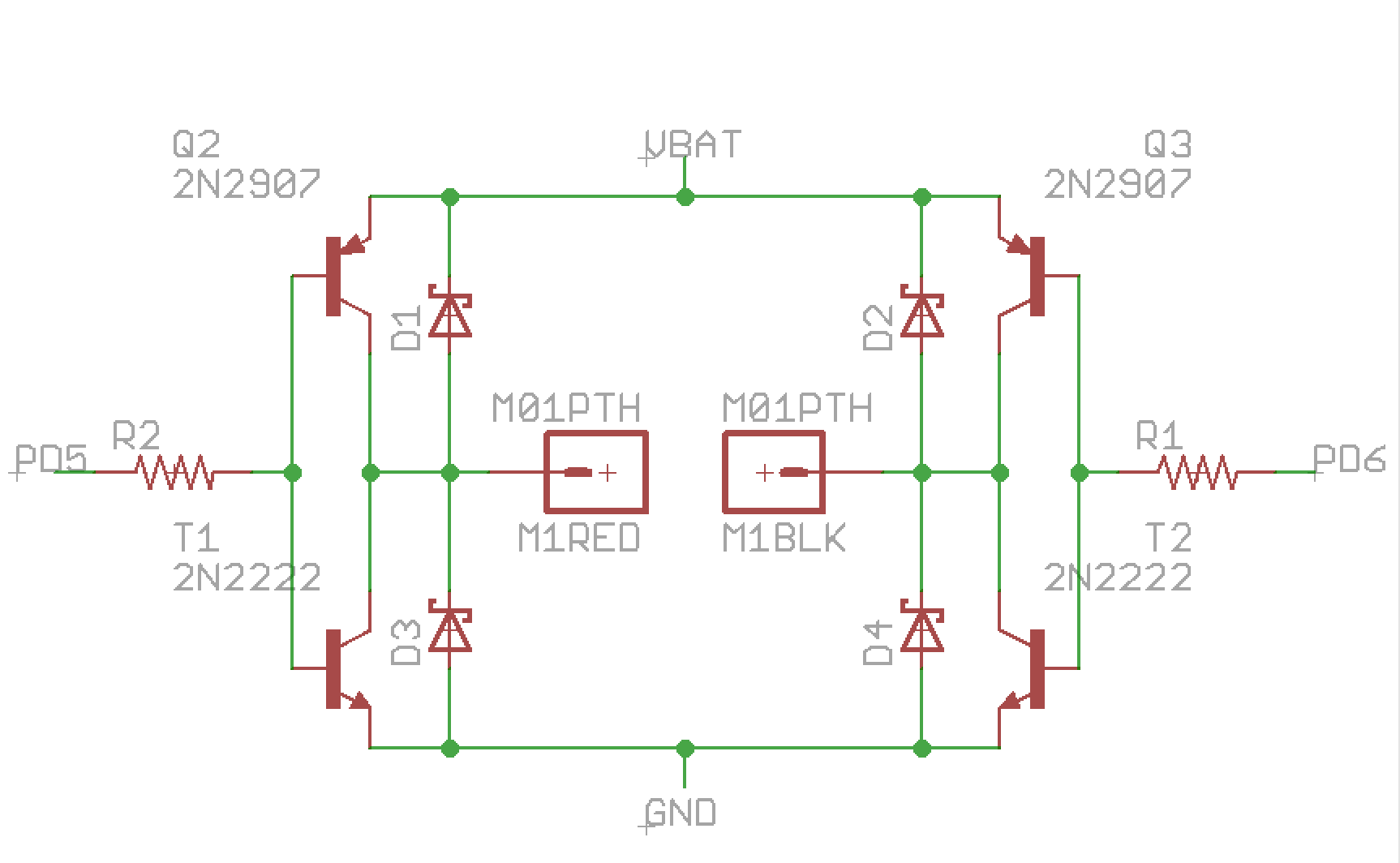
Thanks, Ben. Yes, that is what I was trying to ask - rather than hooking up both inputs to a PWM pin, can I just hook one of them up to a PWM pin and the other just to a regular digital pin. I understand what you mean about one direction alternating between drive and coast rather than drive and brake, but I think the way my H-bridge is wired, coast mode is not available anyway. That is, I have the transistors on the left side of the H-bridge connected and the ones on the right side connected so that I only need two inputs, and thought the Pololu ones did too.
I wouldn’t use PD6 since I’m trying to see if I can free up OCR0A, but used it here to ask if that would work the same way and still alternate between driving and braking without ever coasting. That is, I always hold the left side of the H high or low and then just use the PWM to vary the right side of the H, which I thought would make it go from driving to braking - either high side braking or low-side braking - but never coasting since two transistors are always on, right? But I’m still new to this and may be misunderstanding. I really appreciate your help and advice.
I’m trying to embed an image of my basic BJT H-bridge, but I don’t think the img tag is working, at least it shows up as broken in Preview. It’s here: dropbox.com/s/3tipqhdauu4k38z/H-bridge.png)
That control method should work just fine; however, you should be aware that in one direction you are alternating between drive and brake low while in the other you are alternating between drive and brake high. Brake high and brake low will be functionally the same, but brake high can be dangerous if you are not aware of it since even though the motor is not moving, both motor terminals will be exposing positive side of your battery.
I own 3 of these drivers as well as 3 L298. I’m trying to figure out how to connect them to a new TMC4671 FOC to control a BLDC motor which outputs a 6 PWM signal. The notes of the TB6612 page 4 are confusing because they say it provides for dead time with t1-5. And I can’t imagine how they accomplished that with a single input. Plus on page 7 they have two lines for each motor not one. My suspicion is that IN1 can be used for PWM low. While holding IN2 high, and using PWM as PWM high. Am I making sense? I’ve never hooked up a BLDC motor before. The voltage range and current is fine.
Both of those drivers are intended for driving either two brushed DC motors, or one bipolar stepper motor. They are not appropriate for driving a brushless DC motor. We do not have any brushless DC motor drivers.
Adding to Mr. Patrick’s comment. You can look for BLDC motor drivers at hobbyking. There are many BLDC motor drivers. Choose the appropriate one according to the ratings of your BLDC motor.


