when I drive
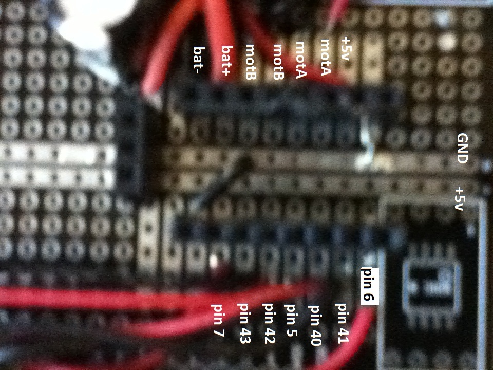
pin5 = HIGH
pin 41 = HIGH
pin 6 = duty cycle(100)
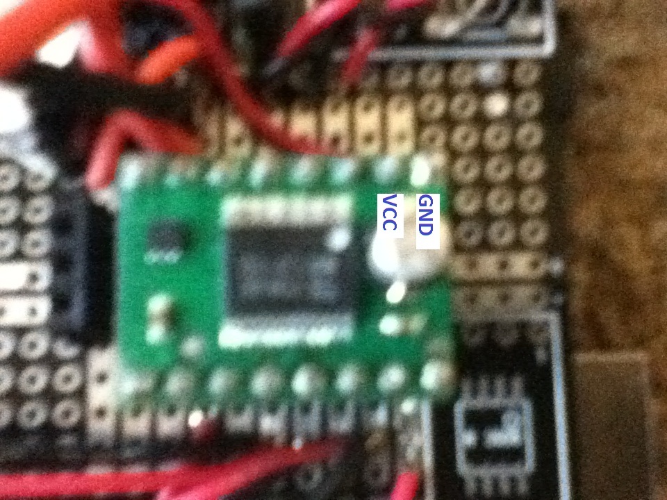
why is it that I don’t develop a voltage across ao1 and ao2?
also my controller heats up to the point where it is hot but does not burn the skin within a matter of seconds but maintains that heat. Does that indicate a short or is that normal??
I don’t see anything wrong with your connections at a glance. Could you take a clear picture of your setup showing all the connections so we can double-check your wiring?
When you say that your “controller heats up”, are you referring to your Arduino or to the TB6612FNG driver? If the driver heats up when only power is connected, it’s likely that it’s been damaged in some way that caused an internal short.
So what then when I provide batter power and Vcc then it should not heat up at all? like cool to the touch? (by the way it only seems to heat up once it is provided with vcc.
[quote=“greenbean209”]
So what then when I provide batter power and Vcc then it should not heat up at all? like cool to the touch? (by the way it only seems to heat up once it is provided with vcc.[/quote]
Yes, the driver should not heat up at all unless it is supplying a significant amount of current to the motors. If it is heating up without motors connected, it is probably damaged. Just to make sure, though, have you double-checked all your solder joints to make sure you don’t have any accidental shorts (and that the joints are providing good electrical connections where they should be)?
If you email us with your order information and reference this thread, we might be able to at least offer you a discount on a replacement driver. However, I encourage you to continue trying to figure out how the first one was damaged, because if there is an issue with your setup, it is likely to just break the replacement the same way unless the problem is corrected.
I appreciate the pictures, but they are too blurry for me to be able to see much in them. If your camera has a macro mode (usually represented by a flower icon), that should help it focus on close-up objects. It would also help if you take a shot from farther out showing both the driver and your Arduino so that I can easily trace the wires going between the two.
Well the thing is its plugged into a socket that I soldered to a pcb.(nktronics arduino mega proto shield. I’ve continuity checked everything to find shorts and I can’t find a thing. Where specifically should I look for a short? What would cause it? Like a a short between what pins?
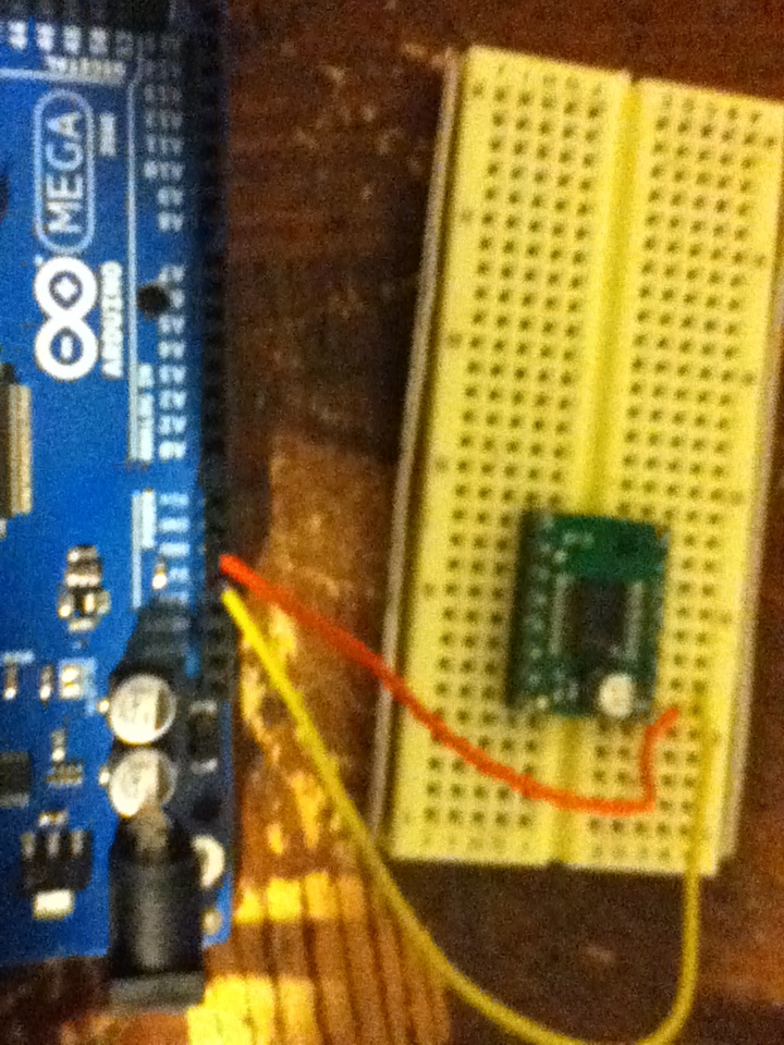
Ill try breaking it out with some jumper wires to see if I can get a different result. How about you give me an example circuit with an arduino? That way I can follow it exactly and if that fails then I know my product is defective or damaged.
the yellow is the +5v and the orange is the ground.
with this setup the driver begins to heat up. This should not happen correct?? All I’m doing is powering the logic!
edit: my multimeter also indicates the resistance between the vcc and gnd pin is 38.4 ohms. So that sounds normal right? so i cant see why that would be shorted… or am I wrong?
You definitely should not be measuring 38.4 ohms between VCC and GND; I measured a board here and the resistance between the two pins, with nothing else connected, was beyond the ability of my multimeter to measure (past the megohm range).
One last thing you could try is to check for any flux deposits left on your board from soldering the headers. They can often be conductive enough to cause weak shorts, and others have had problems with that in the past.
ah but in that case the short would be through the flux and not through the IC correct? I still do have little glazing of flux here and the but I cant tell by looking if its capable of creating a short. Is there anything I could do to ensure that it is not shorting anything?
I’m pretty baffled because I’ve soldered over 50 headers on my pcb and not a one has short do to flux…
Everything on my pcb is as it should be. Nothing is high when it should be low, all the polarities are correct. When the driver is powered and starts to heat up it doesn’t even give off that “hot electronics” smell.
Is it possible that I’ve received a defective driver?
Edit: as an even more direct response to that flux comment, when I measure the resistance between Vcc and GND in these two manners:
from Vcc to the adjacent GND to the north R = 38.4ohm
from Vcc to the GND at a dog leg right to the south R = 38.4ohm.
So I would think that the flux would influence the measurements if it were truly shorting the pins.
All of the grounds on the board are connected, so I would expect the resistance between VCC and any of the ground pins to be the same. However, you are correct that a short caused by flux would probably not cause the driver chip itself to heat up, so that isn’t likely to be the problem.
It seems fairly certain that your board is broken at this point, although it isn’t apparent to me how it could have become damaged. We do test each board before it ships, so it probably worked originally, but it’s possible you might have received a defective board.
We should be able to help you out with a replacement, so please email us directly.