
How to check a4988 driver and dvr8825 working or not?
How to operate stepper motor without arduino and micro controller?
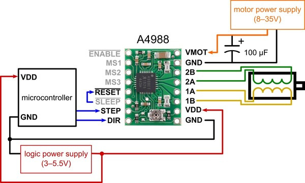
One way is to follow the minimal wiring diagrams given in the pololu product pages. You can make your connection exactly according to the wiring diagrams. Then follow the Step (and microstep) size chart. For example, A4988’s chart is like the following:
| MS1 | MS2 | MS3 | Microstep Resolution |
|---|---|---|---|
| Low | Low | Low | Full step |
| High | Low | Low | Half step |
| Low | High | Low | Quarter step |
| High | High | Low | Eighth step |
| High | High | High | Sixteenth step |
You can change the values of MS1, MS2, MS3 and see if your stepper motor is behaving according to the chart.
You can run a stepper motor with a a4988 driver and Timer 555 IC if you do not want to use a microcontroller/Arduino.
1 Like
I dont know where is the ckt? But i you tube one ckt same like 555 and a4988 driver ckt. I donig same like but ouput not came. U said MS1,2,3 FULL AND LOW PITCH but i am not connect this. Because wuth out ms123 connection it will show full pitch. Thats is reason how to check 4988 working or not… I am also checking another method 74f14pc and dvr8825 ckt but it also same but motor having vibrate once when supply t<1 sec after it was stop. What i am mistake i don’t know ibwant know what the problem… How to run stepper motor these drivers
I think Mr. Brandon can give you a better guideline about the pololu stepper motor drivers and potential chances of mistakes. @BrandonM
Hello.
You can test the stepper motor drivers by connecting them properly and powering them up; they should energize the stepper motor when power is applied. After that, you can manually connect the STEP pin to a high signal to make sure the motor steps as expected.
As far as the proper connections without a microcontroller, for the most part, you can follow the minimal wiring diagram from our A4988 carrier’s product page:
However, since you want to test it without a microcontroller, you will need to address the STEP and DIR pins. On the A4988 carrier, they are not pulled to any particular voltage internally so I recommend adding a pull-down resistor to each pin to make sure they are not floating. Anything between 10kΩ and 100kΩ should be fine.
After that, you can use a jumper wire to manually connect and disconnect the STEP pin to the logic voltage, which should cause the motor to step each time.
The same connections and procedure should work for the DRV8825 carrier as well; however, the STEP and DIR pins on that board are pulled-low internally, so you do not need to add extra pull resistors.
If you are still having problems with your drivers after that, could you provide more details about your setup and how you are using them? Information about your stepper motor, power supply, and what you set the VREF voltage to on the driver would all be very helpful. Also, could you post pictures of your setup that show all of your connections?
By the way, I deleted the post you made in a different unrelated thread asking about this same issue since you already have your own thread about it.
Brandon