I’ve been debugging a control issue with my Pololu 37D motors and Roboclaw 2x7As which seems to be addressed now, but a technician at BasicMicro suggested I add bypass caps to encoder ground and to the motor case to clean up spikes on the encoder signals. I’d like to run this by you for a second opinion.
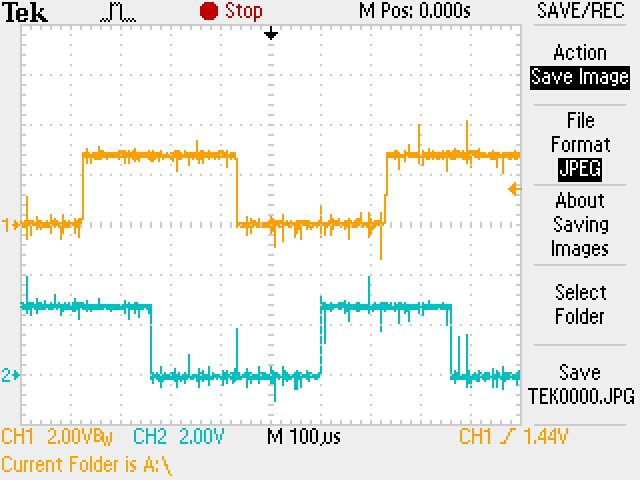
First, here is a scope capture of the two encoder lines from one motor. It was measured at the Roboclaw pins:
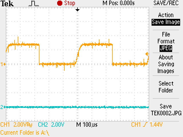
Next, this is one of the encoder lines with a 0.01uF cap inserted to encoder ground at the Roboclaw pins. Note the slightly sluggish rise time:
Do you think the amount of noise on the encoder lines is an issue, and if so, does the 0.01uF bypass cap address it? I got further advice to place the caps near the motor, so I’m wondering if it’s advisable to pop off the motor’s dust cover and look for someplace to solder? Note that there is only 4" of wire from the motor to the controller, so I’m wondering whether it will make much of a difference. Finally, can you suggest a test to see whether the Roboclaw is actually seeing spurious encoder transitions as a result of these spikes? Just eyeballing it, I’m seeing smooth motion so I’m wondering if any of this is really an issue. Thanks in advance for your experience and expertise.
The noise you are seeing on the encoder lines may be getting picked up by your wiring or by how you are probing it. Could you post some pictures of your wiring including how you are probing the encoder signals?
Here’s a picture of my encoder wiring. I made a little extension header for the encoder input pins and that’s what the probe tip is connected to. The probe ground goes to one of the ground pins on the SN inputs but not to the actual encoder ground pin. You can see the encoder wires snaking down a hole in the platform just to the right of the Roboclaw. Directly under that hole is the encoder cap of the Pololu 37D motor.
I cannot see your whole setup from that picture, but the wiring is likely a big contributor to the noise. To figure out how much this is contributing, can you try connecting your probe to ground in a similar way. I suspect that you will see at least a substantial part of that noise on the supposedly grounded input because your wire loop area is big enough to pick up a lot of noise.
Ooof, I’m sorry to waste your time Patrick, but I just figured out what I was doing wrong. I was taking oscilloscope ground from farther upstream than I remembered. When I connect as pictured, the quadrature signals are completely noise free. Thank you so much for your questions because I wouldn’t have revisited my test setup if you hadn’t asked about it.
