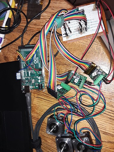
Here is an example of how to use I2C with 2 Pololu controllers (I’m using a 36v4):
tic-arduino/examples/I2CMulti at master · pololu/tic-arduino (github.com)
I can use this code to run 2 stepper motors around as a sanity check. I’m using an ATMega2560, and there are is a 100Kohm pullup resister to 5V for both SCL and SDA lines. The ATMega2560 is connected at Vin to 1 of the 3 Pololu 36v4’s 5V (output) lines to provide power. The schematic I followed is described here:
Pololu - 4.6. Setting up I²C control
The stepper motors are three of the:
Pololu - Stepper Motor: Bipolar, 200 Steps/Rev, 35×28mm, 10V, 0.5 A/Phase
I’m providing 12V from a power supply with adequate current to Vin on the 36v4. I had started at 10V which was almost not enough current, so I think this is adequate now.
It all works fine. The stepper motors move one way, pause, and then move the other way, as the example provides.
That is, it works fine as long as I don’t plug the Arduino’s USB connector into my PC. Then suddenly I get yellow lights flashing and there is no more movement by the stepper motors.
Since I will eventually need to use serial commands over a USB connection, I’ll need to understand how to work around the stepper motor controllers failing when the USB to the Arduino is plugged in to a PC.
In the Tic Controller Center Software, I only changed each 36v4’s I2C ID (from 14 to 15 and a 3rd controller from 14 to 16). But I did not change any other settings on the controller.
But my suspicion is that this is probably an issue on the Arduino side.
Any ideas on how I should go about troubleshooting this, or insights into what needs to be changed would be appreciated. This is a very simple example, and I imagine it can be reproduced easily too.

