
Hello
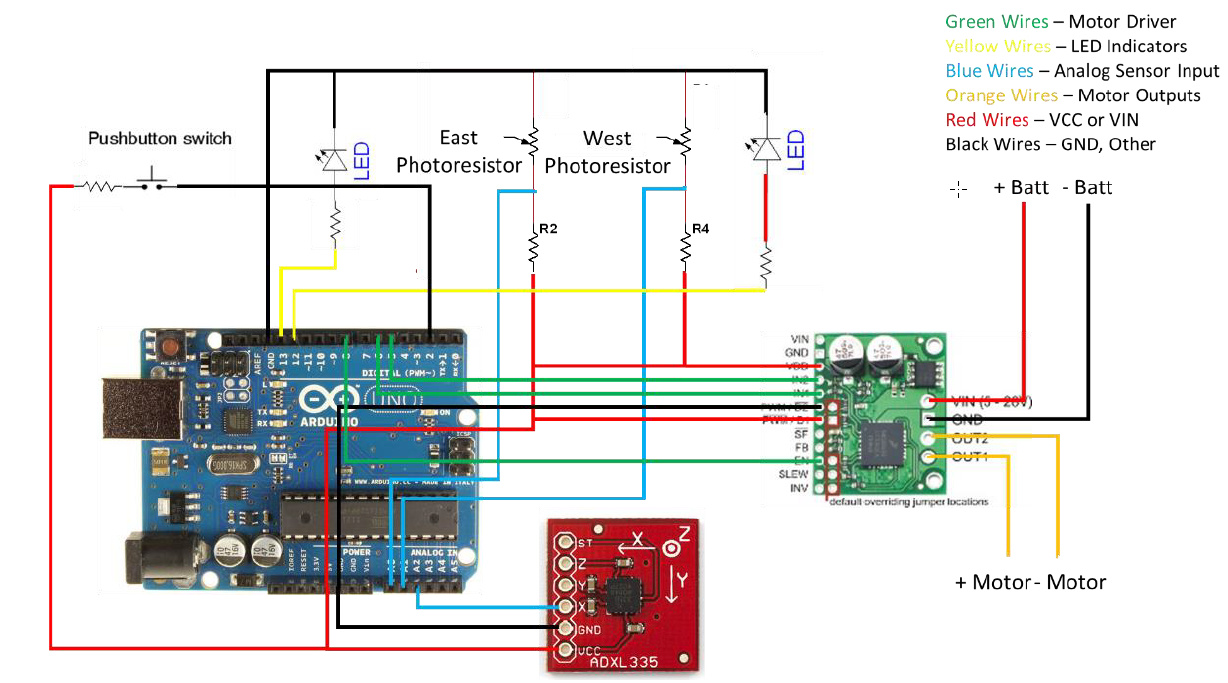
I have a plan for Solar Tracker with Arduino, where I used your unique driver (Dual MC33926 Motor Driver Carrier), But when I close the circuit in the shape below, the command is not sent to the motor, It seems that the code works because when I cover the east or west sensor, the corresponding LED flashes but does not send to the motion command motor, I’ve included the code below.
Thank you for your guidance
It should be noted that I now use a motor and then I use two motors.
my code in arduino
int motorCW = 5;
int motorCCW = 6;
int enable = 8;
int lightCCW = 12;
int lightCW = 13;
int mode = 0;

void setup() {
  // put your setup code here, to run once:
pinMode(5, OUTPUT);
pinMode(6, OUTPUT);
pinMode(8, OUTPUT);
pinMode(12, OUTPUT);
pinMode(13, OUTPUT);
attachInterrupt(INT0 ,modeChange, RISING);
Serial.begin(9600);
}

void loop() {
  // put your main code here, to run repeatedly:
float voltage1, voltage2, comp, angle;

// Retrieve the voltage readings from the light sensors.
voltage1 = getVoltage(0);
voltage2 = getVoltage(1) - 0.09;

// Prints the current mode
Serial.print("Voltage 1: ");
Serial.print(voltage1);
Serial.println();

// Prints the current mode
Serial.print("Voltage 2: ");
Serial.print(voltage2);
Serial.println();

if(mode == 0){
// Sets the panel to 90 degrees when the light sensors have low light
if((voltage1 < 1) && (voltage2 < 1)){
gotoAngle(90);
} else {
// Gets the current angle of the panel.
angle = getAngle();
// Prints the current angle
Serial.print("Angle: ");
Serial.print(angle);
Serial.println();
// Compares the voltages between the two light sensors.
comp = abs(voltage1 - voltage2);
if(comp < 0.0075) {
// Turns both LEDs on if the panel is in the correct sensor positions
digitalWrite(lightCW, 5);
digitalWrite(lightCCW, 5);
// Sets the system delay to 1000ms. This is the rest time between sun tracking movements.
motorStop();
delay(1000);
} else if(voltage1 < voltage2) {
digitalWrite(lightCW, 0);
digitalWrite(lightCCW, 5);
// Only moves the panel if is greater than 30 degrees.
if(angle > 20){
// Controls the motor movement using the voltage comparison between the two photoresistors
motorMove(voltage1, voltage2);
} else {
motorStop();
}
} else {
digitalWrite(lightCW, 5);
digitalWrite(lightCCW, 0);
// Only moves the panel if is greater than 30 degrees.
if(angle < 160){
// Controls the motor movement using the voltage comparison between the two photoresistors
motorMove(voltage1, voltage2);
} else {
motorStop();
}
}

// Delays the motor movement by 5ms
delay(5);
}
} else if(mode == 1){
// Turns the LEDs off if in Accelerometer mode
digitalWrite(lightCW, 0);
digitalWrite(lightCCW, 0);
// Goes to an accelerometer angle of 90 degrees
gotoAngle(90);
// Delays the motor control by 50ms
delay(50);
}
}
float getAngle(void){
// Reads the accelerometer voltage
float angleVoltage = analogRead(2);
// Converts the accelerometer voltage into an angle
angleVoltage = (angleVoltage - 396) * 0.826;
// Returns the panel angle
return angleVoltage;
}
void motorStop(){
// Clears the inputs to the motor.
digitalWrite(motorCW, 0);
digitalWrite(motorCCW, 0);
digitalWrite(enable, 0);
digitalWrite(lightCW, 0);
digitalWrite(lightCCW, 0);
// delay(10000);
}
void motorMove(float comp1, float comp2){
float scale;
float angle;
// Gets current angle from the accelerometer
angle = getAngle();
// Sets the scale for the pwm controlled motor speed
scale = 75*(abs(comp2 - comp1))/max(comp1,comp2);
if(scale < 30){
  scale = 30;
}
if(comp1 < comp2){
// Enables the motor driver
digitalWrite(enable, 5);
// Set the direction and speed of the motor
digitalWrite(motorCW, 0);
analogWrite(motorCCW, scale);
} else {
// Enables the motor driver
digitalWrite(enable, 5);
// Set the direction and speed of the motor
analogWrite(motorCW, scale);
digitalWrite(motorCCW, 0);
}
// Prints the current angle
Serial.print("Scale: ");
Serial.print(scale);
Serial.println();
}
void gotoAngle(float angle){
float currentAngle;
// Only runs when the panel is not at the correct angle
while(int(angle) != int(currentAngle)){
// Retrieves the current angle from the accelerometer
currentAngle = getAngle();
// Doesn't tell the motor to move unless the panel position is further than 1 degree out of sync
if(abs(currentAngle - angle) > 0.85){
// Calls the motor control function
motorMove(angle, currentAngle);
// Prints the current angle
Serial.print("Current Angle: ");
Serial.print(currentAngle);
Serial.println();
// Delays the function for 50ms
delay(50);
if(mode == 0){
return;
}
} else {
// Calls the motor stop function
motorStop();
}
}
}
void modeChange(){
// Changes the mode when the INT0 interrupt (Pin 2)
mode = !mode;
}
float getVoltage(int pin)
{
return (analogRead(pin) * 0.004992914);
// This equation converts the 0 to 1023 value that analogRead()
// returns, into a 0.0 to 5.0 value that is the true voltage
// being read at that pin.
}