I am building a demo robot for my classes. I am using a raspberry pi with 8 SMCs in a Daisy Chain (4 Pololu Simple High-Power Motor Controllers 18v25 and 4 Pololu Simple High-Power Motor Controller 18v15). My test serial code worked very well with 2 SMCs. But scaling to the 8 SMCs has been problematic. I am throwing serial data errors. It seems to involve wiring issues. I used the “Microcontroller with TTL UART” diagram. Can someone confirm the best wiring for a Daisy Chain?
I am using:
TX of my Raspberry Pi to RX of all SMCs,
TXIN to TX of SMC 2,
TXIN SMC 2 to TX of SMC 3, …
Ground pin of Raspberry Pi to all grounds
This connection gives me a instantaneous serial data error. Also if I go back to a very simplified system it appears as if the error is hung and I must use the SMC control program to clear the controllers. Is there a serial command that can clear all errors before sending commands to the SMCs?
Thanks
Frank Wood
Hello, Frank.
Your wiring description sounds correct for the SMC. How did you determine the error is a serial error and why do you think it is due to a wiring issue?
Can you post your entire code for the Raspberry Pi? Also, can you provide more details on your simplified system (e.g. components and connections) and clarify the steps you took when switching between your setup with 8 daisy-chained SMCs and your “very simplified system”?
Regarding your last question, it sounds like you are looking for the Exit Safe Start command, which clears the safe-start violation that prevents the motor from running. (The Safe-start violation error is enabled by default, but you can disable it by checking the Disable safe start option in the Miscellaneous box under the Advanced Settings tab of the Simple Motor Control Center.) You can find more information in the Simple Motor Controller User’s Guide.
- Amanda
Thanks Amanda. I can answer some of your questions hopefully before your day ends. Then do the rest for homework (teacher lingo). I have the motor control center software connected to the first SMC using a PC and am simutaneously sending serial commands through python from my Raspberry Pi. I can see all errors and the “serial errors” issue is the only one that is popping up. I am disabling safe start by (0xAA) in my code and that is working fine. The serial errors were evident when I connected the Daisy Chain, before I ran any code. This is why I think I have a wiring issue.
The bottom line is that I can run one motor with the daisy chain (the other 7 SMCs) disconnected with my python code but have yet to get my daisy chain wiring to work. At one point it was acting like the error code was still represented after an obvious error was fixed. Since the motor control center has a button for “Resume” I thought that you might be able to send a serial string to duplicate that command.
I have been establishing the ID number of each SMC in the control center and then addressing each one individually. I am going to work through the code later tonight and then try it again. It seems strange that you can connect all of the SMC RXs to the one Raspberry Pi TX.
FYI: I first wired up all this on a Hat for my Raspberry Pi, when that did not work I tried making a very nice looking second try. When both failed, I went to bread board. Then to just one SMC.
Thanks Again. I will work on my code tonight.
Hello.
It is hard to follow all of the different setups and tests that you have done. For example, in your first post you say you had it working well with 2 SMCs, but in your latest post it sounds like you can only get 1 to work. I suggest making it as simple as possible and slowly scaling up once it is working correctly. Could you start with only a single SMC connected and see if you get the serial errors? If you do get serial errors, which ones are showing an occurrence count in the "Simple Motor Control Center?
If you can successfully control one SMC without serial errors, can you try adding a second (wired for daisy-chaining like you described) and doing the same test? If you get serial errors when adding a second SMC, can you post pictures of your setup that show all of your connections as well as the settings files for each SMC? You can save the settings files by selecting the “Save settings file…” option within the “File” drop-down menu of the Simple Motor Control Center. A copy of your simplified (but complete) Rapsberry Pi code would also be helpful.
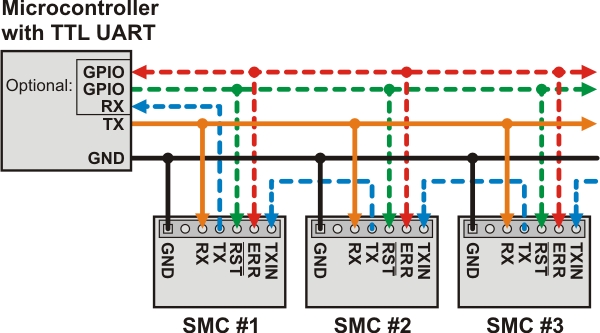
By the way, since you sound unsure about your connections, you might find this diagram for controlling multiple SMCs from a single TTL serial source helpful (please note that the yellow and green dashed lines connecting the RST and ERR pins to the microcontroller are optional). More information about this can be found in the “Connecting a Serial Device” section of the Simple Motor Controller’s user’s guide:
Brandon
Thanks Brandon for the response. I realized that I bench tested a raspberry pi version 2 and built the daisy chain on a raspberry pi version 3. I found some earlier posts that explained the problem with serial on rev 3. I tried implementing the fix but ran out of time. I can’t use the version 2 because it eats up one of the usb connections for the wireless adapter.
I have been using the diagram that you put in your post, however the drawing looks like the (orange wire) TX of the Microcontroller feeds the RX of each smc in parallel. According to the drawing, it looks like you could bundle all of the Orange wires together and connect to the TX of the microcontroller. Is this true? I made a raspberry pi hat that did this and I immediately received serial errors. (but at the same time I was having apparent config.txt problems with version 3) Also, the BLUE TX loop back is “dotted,” does that mean that if you feed the RX pins on the smcs and ground everything to the Microcontroller; that you do not need the blue TX to RX loop back?
Thank again for your help.
The TX pin of the microcontroller should be connected to the RX pin on all of the SMCs being daisy chained. The blue dashed connections in that diagram are optional if you do not need to get any information back from the SMCs and only need to send commands to them. If you are using any commands that return information back to the microcontroller, you would need to include these connections.
Have you tried any of the things I suggested in my previous email? Which particular serial errors are you getting? Did you get any errors when trying to control a single SMC, if not, what happened when you added a second? Also, I would still be interested in seeing the settings files for your SMCs as well as the simplified but complete Raspberry Pi code.
Brandon
I have it working. My problem was in the config.txt of the raspberry pi. I saw the issue in another forum post. If you are using a raspberry pi 3 you must include “enable_uart=1”. Lots of reasons, but anyone interested can read about it https://www.raspberrypi.org/documentation/configuration/uart.md I complicated the problem by mixing up version 2 Raspberry pi boards with version 3. So I would get mixed results.
My test code is here (note I borrowed from others to create this code):
import time
import serial

ser = serial.Serial(
    port='/dev/ttyS0',
    baudrate = 9600,
    parity=serial.PARITY_NONE,
    stopbits=serial.STOPBITS_ONE,
    bytesize=serial.EIGHTBITS,
    timeout=1
)
         # designated all stop routine
packet4 = bytearray()
packet4.append(0xAA)    # safe start
packet4.append(0x0A)    # 10 unit addressed
packet4.append(0x60)    # stop command
packet5 = bytearray()
packet5.append(0xAA)   # safe start
packet5.append(0x0D)   # 13 unit addressed
packet5.append(0x60)   # stop command
try:
    while True:
        # in theory, the joystick commands would be interperted and corresponding
        # values would be passed to speed and direction variables
        # Each packet would represent one SMC/motor and all would be written via
        # ser.write() each loop. If there is a keyboard interrupt it would kill the loop
        # When the loop dies, the stop packets are called.

        packet2 = bytearray()  # initiate an empty bytearray() to hold commands
        packet2.append(0xAA)   # safe start
        packet2.append(0x0A)   # 10 unit addressed (unit 10)
        packet2.append(0x05)   # forward command
        packet2.append(0x00)   # first part of speed info
        packet2.append(0x32)   # second part of speed info; half speed

        packet3 = bytearray()
        packet3.append(0xAA)
        packet3.append(0x0D)   # 13 unit addressed (unit 13)
        packet3.append(0x05)
        packet3.append(0x00)
        packet3.append(0x32)

        ser.write(packet2)
        ser.write(packet3)

except KeyboardInterrupt:
    ser.write(packet4)
    ser.write(packet5)
The append method seems cleaner to me to create a string of hexidecimal commands. The command reference can be found in the “Pololu Simple Motor Controller User’s Guide.”
Thanks to Brandon and Amanda for the help.
FYI for anyone reading this post. My project was to develop a heavy duty 12v 25+amp capable system to move a robot. The canned solutions that Adafruit has are for low power systems. Quite honestly that bores the engineering class I am teaching. My robots are designed to be as large as a mini frig and very powerful. I tried several different Pololu products to develop a kid proof system to move the robot and the SMCs are the best. I have 4 - 12 volt CIM drive motors that that are driven through gears. The Pololu G2 High Power Motor Driver 18x25 theoretically should do the job if you call it from an Arduino. But I was never satisfied with passing command parameters to a raspberry pi, then having an Arduino pass PWM parameters to the the High Power Motor Controllers. I can control the PWM easily on the SMC from serial commands from the raspberry pi. Much cleaner system. I also developed a hat for the raspberry pi to make the wiring cleaner.
I have already established a system of controlling robots through an xbox 360 wireless controller and a raspberry pi. So my next step is to merge the my previous work with this project. Because I am using VEX Mechanum Wheels (can go in any direction), the control logic is going to be a bear. If you would like more information on lessons learned, reply to this thread and I will share.
2 Likes
