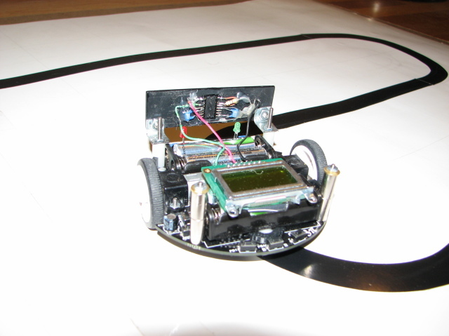
Got sensor mounted and wired on a 1" x 3" piece scrap plastic. Temporarily attached it to front of 3pi. Added a few lines of C code to stop motors when output of sensor goes low of the PID Line Follower program. Wow, it works great! Stops 3pi within 3" of piece of white paper. Then tried the white box 3pi came in, standing vertically on the track. Stops perfectly. Now, tried palm of my hand. Same super result, stops within 3".
Only problem. It was real challenge for me to wire up the sensor. The pins are NOT DIP spaced. That is, pin spacing is 1.5 mm. And the pins are very fragile. Ruined one sensor already. All parts and wires have to be stabilized, so nothing moves. I used a hot glue gun after soldering. Watch your fingers. The stuff is very hot!
Had to put a bit of balance weight at back of 3pi. Used some nuts and washers on 2 3-48 screws. Put screws in 2 holes on PCB that are for the Expansion Kit upper deck in the rear of the 3pi.
Next, maybe make 3pi swerve around something white on the track.
I’m glad to hear the new sensor is working out well for you. Please keep us updated on your project’s progress, and I’d love to see pictures if you have a chance to take any!
Thanks for reply. Moving sensor board a bit closer to front of 3pi, lowering it somewhat. Will take picture when done and send it. Again, I see lots of “viewers”, and very few “repliers” (you and I) and on mostly all forum messages. Maybe, a little editorial about this phenomenon could be posted by one of the Pololu administrators. But, then maybe not.
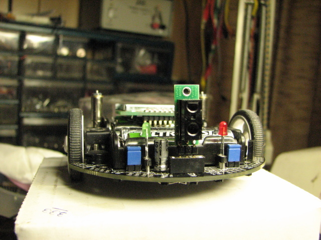
Kind of a beta mounting of Sharp sensor, but it does work great, stopping or turning 180 when sensor “sees” obstruction. I use PD0 to discover a low, and then do something. Works within 3 to 4", very fast and cool.
Thanks for the pictures, Donde. Your mounting job looks very nice! Would you be willing to post your code for those who might be interested in trying something like this for themselves?
Here is code portion I used to do two tasks. First, stops 3pi when sensor sees object, then continues when object removed. Second, turns 3pi 180 when sensor sees object, then continues.
donde
while(1)
	        {	// PD0, bit 0 set to input, with pull-up
			if(PIND & (1 << PD0))		// Normally high, if low, sensor "sees" object
				break;

			if(get_ms() <= 33000)  {	// 1st 3 laps, object 3pi stops, no object 3pi continues
				set_motors(0,0);
				left_led(0);
				right_led(0);
				}

			if(get_ms() >= 33000)  {	// Last 3 laps, object turns 3pi 180, no object 3pi continues
				set_motors(80,-80);
				delay_ms(400);
				break;
				}
               }
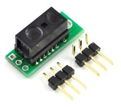
When looking at this sensor I found it strange that it has so many leads compared to Sharp GP2Y0D340K digital sensor. This was the reason that I stayed with 340s wherever I could in my projects.
It may be nice if someone (Pololu?) could sell small cheap PCBs for mounting 810s and necessary parts (thru-hole or SMD). Like 0.5 x 0.8 in. On the other side it would only have 3 output leads: “+”, ground and data.
True Rio, this sensor is really an OEM sensor, made to be very small for special purposes, like water control in restrooms. Don’t think Sharp has 'bot people in mind. A bit of a challenge to wire, but was worth it, since it works as advertised. And it is very light, but my mounting did unbalance the 3pi, so I added some counter weight at back using screws and metal spacers.
I mentioned to Pololu heads, it might be neat to put the sensor and parts on a tiny board with the 3 leads terminated on a header. They are looking into it. Again, if you wire it up, be careful of the sensor pins. I would buy more than 1 for insurance.
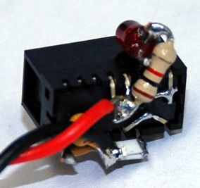
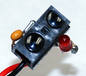
The sensor carrier PCBs are on their way, and if they work, they should be available by the end of the month. I’ve also attached pictures of my initial test setup with these sensors (the LED turns on when the sensor is detecting something). It’s a little tricky but certainly doable, and that was with two surface-mount resistors stacked in parallel to get close to the desired 4.3-ohm resistance. (The implementation was also a bit nicer before Ben broke it and fixed it!)
This was exactly what I was looking for! I have been having trouble getting my sharp sensor to work in my project. Is there any way you can elaborate on your picture. Is you LED your Vo? and the two wires is that GND and VCC? and how are the capacitors and Resistors connected?
We’ll have the carrier board out soon, so we’ll be posting a schematic with that. It’s basically just the connections that are shown in the datasheet.
In the pictures, the LED is on the output, and the red and black lines are the power connection. You can see I’ve just broken off a bunch of the unused pins to get them out of the way. Don’t forget to enable the thing and that the output is active low.
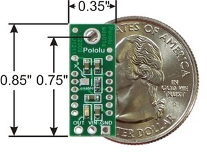
We also sell the carrier board without the sensor for those who already have a Sharp GP2Y0D810Z0F digital distance sensor and for those who want to use this carrier board with the shorter-range GP2Y0D805Z0F distance sensor.
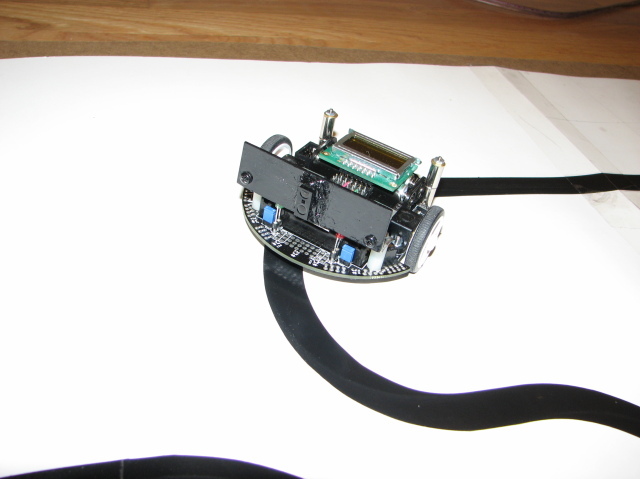
Sharp sensor and carrier board now mounted in place of hand wired version. I used the right bend header. Then soldered a female header on top of 3pi, so sensor can be plugged into it. To left of sensor, I mounted a 10 uF capacitor across Vcc and ground as Pololu suggests, using the leads of the capacitor to connect to the female header. I then ran a lead under the 3pi to PB0 using a 1 pin header. This way, no wires show on top.
It works very good, I think even better. Less front weight, less drag, a bit more speed, although not sure of that. Running at max=120. Next, try wall-follower with analog sensor added and being shipped by you.
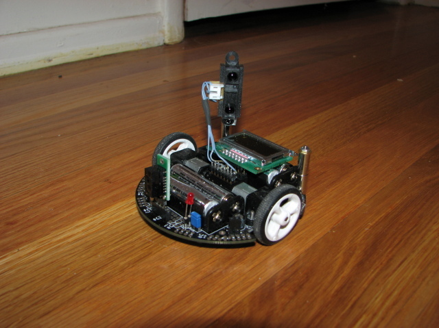
I got the wall-follower project to work great. The front digital sensor checks obstacles right in front of it from 0" to 4". The rear analog sensor pointing left at 45 degrees, checks for obstacles from 4" to 32". I had this one mounted on the other rear side, but found it didn’t detect as well. The present location fires “over the bow”, and picks up objects past the robot chassis, starting about 4" out. It seems to stay clear of almost any object, except blank CDs in the tall round container. I think the shinny plastic does not reflect IR properly.
donde
I’m glad to hear the project works well for you! I like your sensor mounting job, too. Did you have to tweak the program much to get it to work with the Sharp digital distance sensor in the front?