I’ve been having some trouble setting the current limit of my driver. I’ve watched the video on the product page a hundred times but it seems my driver doesnt work like the one in the video does.
When I place my multimeter on potentometer and start turning it clockwise, Vref doesnt change then suddenly itll drop down by 100mV. When I turn it anti-clockwise, same thing happens except the voltage jumps back up. Vref also doesn’t increase past 300mV. Sometimes it’ll stay at 260mV until it suddenly decided to jump back up again to 300. No amount of turning seems to help and the behaviour is completely erratic.
I’ve checked my soldering connections with the multimeter and they’re fine. However, the enable pin is not completely low - its at ~300mV. i dont know why this is, ive checked for shorts and there apperas to be nothing. the driver is also meant to have a 200k internal resistor on enable so it should be low by default. also, Vmot is not powered on, but I saw someone in another post say that it should be? Please help!
Cheers
PS. i dont know the specs or model of my motor but it was previously working fine with the DRV8834.
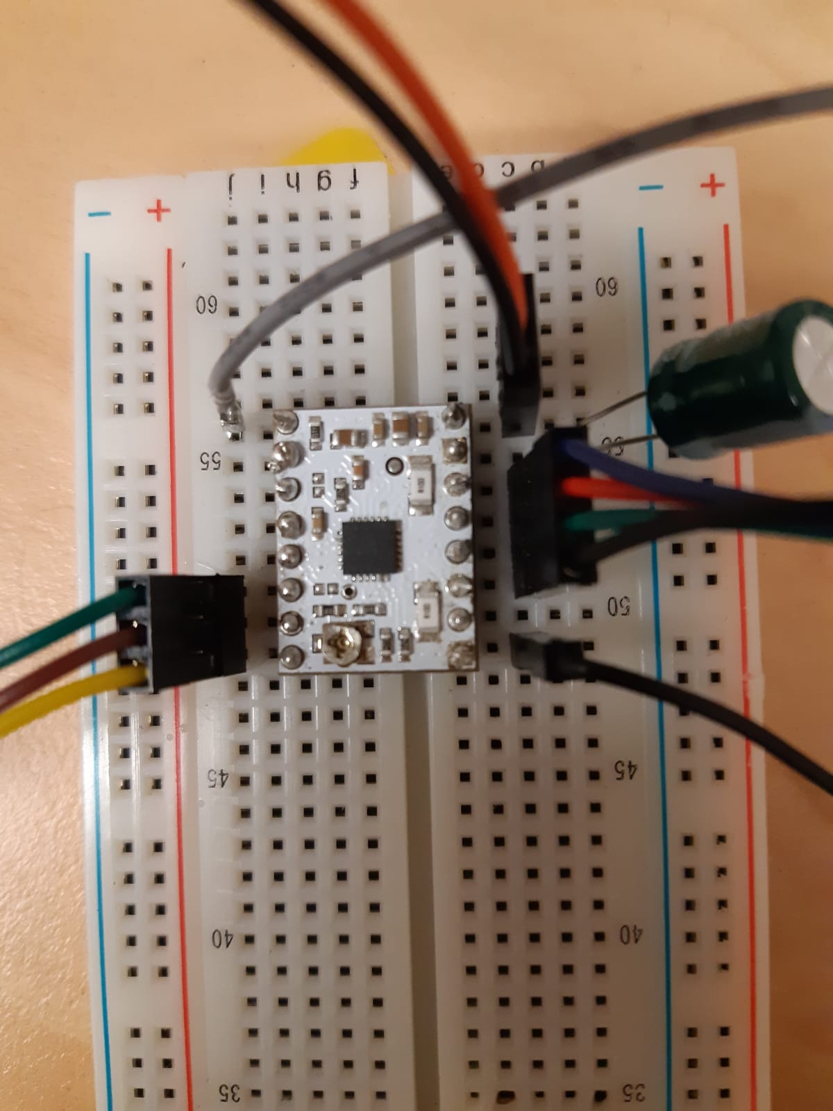
How many degrees are you turning the potentiometer? Can you see the dial of the potentiometer moving as you turn the screwdriver? Are you using a flathead or phillips screwdriver? Can you post pictures here that show your connections, including any soldered connections you made? Do you have the SLEEP or FAULT pin connected to your logic voltage? What kind of power supply are you using for VMOT?
I varied the degree of turning from slow, slight turning to more rapid and drastic turning and I still got the same results. The dial is moving, and I have tried both a flat head and phillips head scredriver but found that phillips head worked better for me. SLEEP is connected via the pi and VMOT is coming in from a powerpoint and 9.82V are being delivered to the motor.
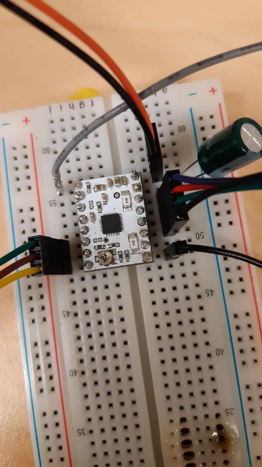
Thank you for posting those pictures. Your two ground connections look like the solder is balled on the pin and not wetting the pad, which can create a poor connection between the board and the pin and prevent the board from receiving power correctly. Also, you have a few other soldered connections that look like they might be unreliable. The Common Soldering Problems section of the Adafruit Guide to Excellent Soldering shows examples of what problematic and ideal soldering connections look like and tips for fixing problematic ones (in general, that guide has a lot of helpful tips for making good soldered connections efficiently). Can you look through that, retouch any connections that look problematic, and let us know how it works? If you are still having problems, can you post pictures that show the retouched joints?
I retouched the solder on the ground pins and enable is now permenantly held low which is good progress. However, the pot continues to behave in the same way i described before -erratic and now only reaching a max of 0.2V.
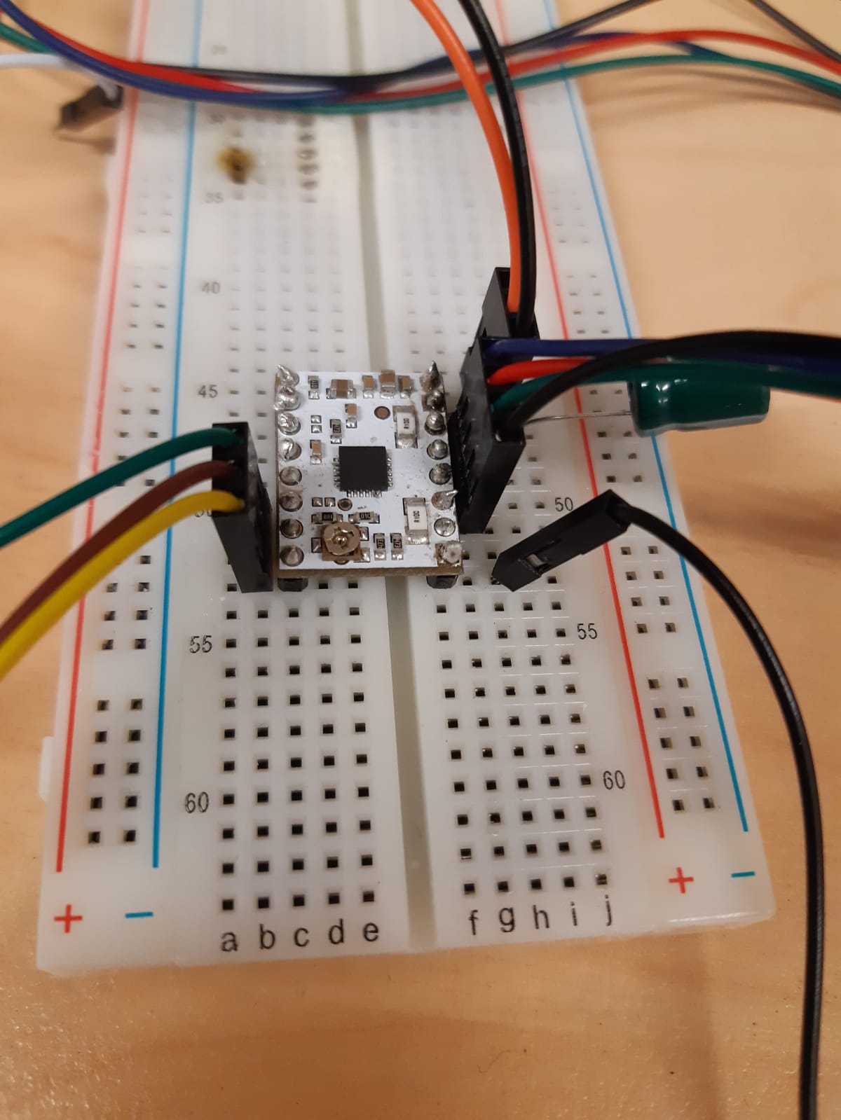
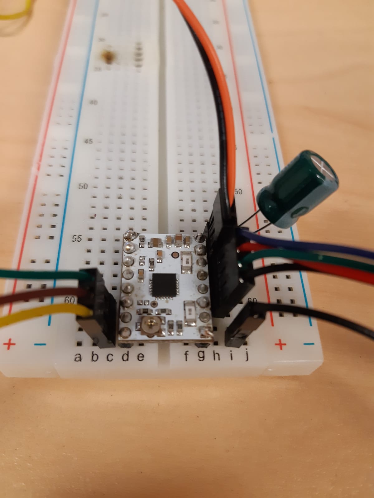
I’ve attached an updated photo of the setup.
Those solder joints still look like they do not connect the pad on the PCB to the pin. A temperature controlled iron can really help when making connections like this. An iron that is too cold won’t melt the solder properly and one that is too hot can oxidize the solder while you are still working with it. Also, when you apply heat to the connection, you should be sure the iron is touching the pad of the PCB so that gets heated and touch the pad with the solder wire. The ground, VMOT, and stepper output connections all have bigger traces than the signal pins, so you might need to heat the pads for several seconds before they are hot enough to apply solder.
At the moment, the motor is holding when plugged in but when the program starts there is no stepping - just a high frequency whistle. I understand that this sounds like a current problem BUT Vref continues to read zero despite how many times i turn the pot so adjusting the current limit is impossible.
Are you trying to measure VREF at the VREF pin (between the SLEEP and CONFIG pins)? That pin requires a solderable jumper to be bridged to be connected to make a reading there. You can read more about that in the “Optional pin jumpers” section of the board’s product page. The VREF voltage can be read at small VREF via between the driver IC and the potentiometer or at the top of the potentiometer without any changing a jumper.
I’ve been measuring VREF at the via or from the top of the potentiometer and I am always getting zero.
I left the motor overnight and when i tried it again this morning it was working fine, stepping at 1/32 but VREF is STILL zero. Now that the motor is working, I can progress but i am still confused at how the VREF could supposedly be zero yet the motor is functioning well.
We would not expect the driver to work very well if there was not a voltage present on VREF. Maybe if you post some pictures or a video of how you are measuring VREF, we can determine what the problem is.