I’m using the DRV8825 (md20a) controller and a #1206 stepper (4.5V/670ma) and am trying to setup an appropriate current limit for it. I have a 12V power supply and will be using the controller in micro-step mode (but I’m unsure exactly which mode I’ll be using at this point).
I understand there are 2 ways to set the current limit: measure specific coil current or use Vref. Here are my questions:
-
Do both of these methods result in similar results? Is there any benefit to measuring the specific coil current vs. using Vref?
-
If measuring specific coil current, the stepper needs to be hooked up which may result in the stepper getting too much current (since I have no idea what the pot is set for at this point). Should the pot be moved to a specific position before starting the measurement? When doing this, only 1 of the coils should be connected, correct? Should the A or B outputs be used, or does it not matter? Just so I can keep the motor safe, can you list the specific steps to use to do this measurement without damaging the motor?
-
Also, when doing a specific current measurement the product page states that this value will be 70% of the full current, so for my motor (#1206) I’d be trying to set the pot to give a current of approx. 470ma (0.7 * 670ma), correct? Should the full rated current value be used or should something a bit smaller be used?
-
When doing the Vref calculation, should the published stepper current (670ma for the #1206) be used as the current limit value or should that be set somewhat lower? Assuming I should use the published stepper current, the Vref I should set the pot for would be:
Vref = (current / 2) / 0.7 = (.670 / 2) / 0.7 = 0.48V Correct?
When I try to measure Vref with a 12V source, the smallest value I can get with the pot is 0.85V. Obviously doing something wrong … any ideas?
- The current limit calculations outlined on the product page (and several other sections of the provided information) state everything with respect to full-step mode. If intending to use the driver in a micro-step mode, do you have to do anything different when calculating the current limit?
Appreciate any help.
Does anyone have any ideas on this ?? Really would appreciate some help. Thanks.
Hi.
I suggest using the VREF method with the motor not connected to set the current limit; then you could double check it by measuring the coil current after connecting the motor. This helps you set a safe limit before connecting the stepper motor. When setting the current limit with the VREF method use the calculation given in the instructions on the product page:
Current Limit = VREF × 2
A minimum VREF value of 0.85V is not normal. Could you describe how you measuring it and post a picture showing where you are measuring?
Once the current limit has been set in full step mode, the same setting should work while microstepping.
-Derrill
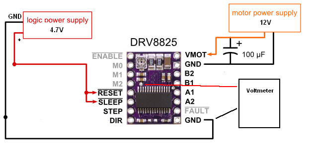
Here’s the setup I’m using to measure Vref (and the minimum I can get is 0.85V):
Can you also please read over my questions #3 & #4 and be sure what I’ve done is correct.
Appreciate the help.
Turning the pot all the way the other way results in a measured Vref of 3.26V. So, the Vref range that I can get with the setup as described in my last post is: 0.85V (min) to 3.26V (max). This doesn’t look correct. Please advise.
Really need some help with this. I can’t move forward with using the DRV8825 until this gets resolved. Do I have a bad DRV8825 or am I doing something wrong? PLEASE ADVISE …
Thank you for the great diagram. I am sorry I missed questions 3 and 4.
-
This calculation is correct.
-
Yes, you should use the current rating as the current limit, which would mean setting VREF = 0.670/2 = 0.34 V. If you know you will only be running in full-step mode, you can actually set the current limit a bit higher since the coil current is always limited to 70% of the set limit. (So if you know you will be in full-step mode, you can safely set VREF = 0.34/.7 = 0.48 V)
Could you please check the resistance across the potentiometer? If you look at your connection diagram, the connection tabs form a “V”. Please measure the resistance across the pot in these positions:
Probes at the base of the “V” and the upper left of the “V”:
   Measure the resistance with the pot turned full counter clockwise

   Measure the resistance with the pot turned full clockwise
Probes at the base of the “V” and the upper right of the “V”:
   Measure the resistance with the pot turned full counter clockwise

   Measure the resistance with the pot turned full clockwise
-Derrill
Here’s what I have:
Probes at the base of the “V” and the upper left of the “V”:
Measure the resistance with the pot turned full counter clockwise 5.73K ohm
Measure the resistance with the pot turned full clockwise 7.2 ohm
Probes at the base of the “V” and the upper right of the “V”:
Measure the resistance with the pot turned full counter clockwise 2.26K ohm
Measure the resistance with the pot turned full clockwise 7.30K ohm
I was able to locate another DRV8825 (md20a) which I have NOT actually tried yet but did check the resistances and got pretty different results as follows:
Probes at the base of the “V” and the upper left of the “V”:
Measure the resistance with the pot turned full counter clockwise 7.38K ohm
Measure the resistance with the pot turned full clockwise 13.3 ohm
Probes at the base of the “V” and the upper right of the “V”:
Measure the resistance with the pot turned full counter clockwise 27.6 ohm
Measure the resistance with the pot turned full clockwise 7.39K ohm
Are these closer to the expected values? What is the issue with the first DRV8825 and can I get a replacement if it is defective (here’s my order # 1J102267)?
It seems you might have a bad DRV8825. Could you please send us an email at support@pololu.com referencing this thread.
-Derrill
I sent an e-mail but I’m not quite sure why you can’t resolve this.
What appears to be the problem with my DRV8825? Does it have the wrong pot installed? Is this something that has occurred before? Do the values I’m showing for the other DRV8825 look correct? I don’t want to risk powering up the new one if it does not look correct. Really not very happy that I’ve now had to spend 2+ days trying to get this resolved and I’m still not sure what the issue is or how it will be resolved.
At this point, I think it would be best to try again with a new driver. We prefer to work out the details of that through direct correspondence rather than on the forum.
It is unlikely your board has the wrong pot, but the pot is not behaving as expected, so maybe it has a defect. This is not something we have seen before. The resistances you are measuring on your second driver look right: at each extreme, the resistance between the wiper and one leg should get very close to zero.
I understand your frustration at how long these things can some times take to resolve, but I hope you can appreciate that our goal is to try to figure out the cause of the problem so that we can identify the best way to address it.
-Derrill
