I’m new to using these motor controllers and linear actuators so pardon me if I ask a stupid question…
I’m trying to set up a PIC micro controller to configure and run the JRK 21V3 controller and to ultimately control the position on my linear actuator. I have done basic tests with the PC and the utility to configure and operate the motor controller and actuator with the USB interface. If I have a dedicated PIC micro controller running a serial interface to the motor controller board, can I completely configure and operate the motor controller with serial commands or is a PC with USB necessary for some configuration? My actuator has feedback available.
Has anyone done this and, if so, would you be willing to share how to set this up?
Thanks.
Hi.
All of the serial commands you can use with the jrk motor controller can be found in the user’s guide under the “Using the Serial Interface” section. For any settings that are not accessible using the jrk’s serial interface, you will have to use some type of USB interface (e.g. our jrk configuration utility or your own PC software). However, these settings typically only have to be set once for most projects.
- Zeeshan
Thanks for replying.
I did read the operating manual and saw the serial commands listed. I didn’t see any commands for setting upper or lower limits, setting PID values, or some of the other commands typically set through the USB interface and the utility program running on a PC.
So in a typical stand-alone (microcontroller only) powering up scenario, I would need a local PC running the control application to set some of the limits and then disconnect the USB for stand-alone operation? Does the motor controller retain any settings when powered down (like in EEPROM) or does the utility program need to be used every time the motor controller is powered up?
I had wanted to use the microcontroller to control the linear actuator in the field without having to use a PC. Is there no way to do this without using a PC?
The settings are stored in non-volatile memory and will persist when you power down the jrk motor controller, so you should only have to configure these settings once.
- Zeeshan
I still apear to be having some problems getting the serial interface to work with the JRK 21V3 motor controller.
I launched the Pololu JRK Configuration Utility program and was able to successfully run the motor out and in. I recorded the max and min values associated with the actuator at maximum and minimum extension. I then scaled the values for the Set Target Low Resolution Forward command (a MAX value and a MIN value). I created a small program on a PIC, which outputs the Set Target Low Resolution Forward command with the MAX value (i.e. 0xE1 0x58, where 0x58 is the max value), waits for about 7 seconds (the time it takes the actuator to extend fully), outputs the Set Target Resolution Formward command with the MIN value (i.e. 0xE1 0x20, where 0x20 is the min value), waits for another 7 seconds for the actuator to withdraw fully, and then repeats. I’ve confirmed the serial commands going to the controller with an oscilloscope.
The manual shows the Set Target Low Resolution Forward command as 0xE1,magnitude.
I set the interface to be fixed serial with a baud protocol of 38400,N,8,1.
What am I missing to get the serial interface to work with these commands?
Thanks.
you might try changing the serial mode and the use the prefix byte as per the manual to sync the baud rate.
‘If your jrk’s input mode is Serial and its Serial Mode is “UART, detect baud rate”, you must first send it the byte 0xAA (170 in decimal) on the RX line (so it can detect the baud rate) before sending it any commands.’
I am sorry you are having problems. Could you post your jrk settings file so I can check your settings?
- Zeeshan
I initially had the fixed baud rate option selected, with a baud rate of 38400. When I saved the file, the baud rate was saved as 38339, for some reason. The motor failed to move when I sent the command 0xE1 0x58. I tried 0xE1 ‘,’ 0x58. It was unclear from the manual whether or not the comma was needed. Still no response. I changed the setting to auto-detect the baud rate and modified my program to send a 0xAA first before sending the 0xE1 0x58 command. Still no response. When I have the USB connected and manually set a target value, the acutator moves to the correct position.
I’m attaching the file associated with the fixed baud rate option.
Any insight would really be appreciated.motor_settings.txt (1.39 KB)
Could you try changing your serial mode to USB Dual Port and try through the virtual COM port using our serial transmitter utility?
- Zeeshan
I downloaded and installed the Pololu Serial Transmitter Utility for Windows. I found the com port number associated with the Command port and made a successful connection. I changed the interface to be USB Dual Port. I formatted the command to move to maximum extension (as determined by scaling the Set Target value) which was 0xE1 0x58. When I entered the command in the two-byte command field and clicked Send 2-byte command, the actuator extended beyond the normal extended value (the actuator wen all the way out and I heard a thump at the end of travel). I formatted the minimum extension command (0xE1 0x20) and clicked Send 2-byte command. The actuator withdrew about half way. I tried formatting 3-byte commands with a leading 0xAA. The results were the same. By the way, the baud rate was set at 9600.
It appears the command port via USB is at least semi-operational. Why doesn’t the serial input mode (either fixed baud rate or detect baud rate) work with the same commands? Is there some other setup needed to accept input from the RX pin? My PIC TX output is connected to the JRK RX pin and my PIC ground is connected to the JRK ground. I have verified the voltage level at 5.0VDC. I have verified the format of the serial stream is non-inverted (normal high, start bit goes low, etc.)
You don’t have the crc selected ‘on’ do you ? I am driving mine from a plc using a max232 converter and did have some communication problems when my wiring was not shielded well and the driver chip was a fair distance from the rx input pin, I am only sending at 9600 btw. It doesn’t take much of an error for the driver boards to not respond properly. Have you tried setting the input mode to analog (0-5v). That could prove out that at least the RX pin is working and is an easy test.
I tried changing the baud rate to 9600. No difference. My microcontroller board is only 6" away from the serial input of the motor controller board. I made sure all the grounds were properly connected. I’m driving the JRK RX pin directly from the output TXD pin of a PICLF252 (pin 17 of the PIC). I changed the settings to accept an analog input on the RX pin (with the utility program) and connected the center tap of a 50K pot to the RX pin. I connected one end of the pot to the JRK 5V regulated output and the other end of the pot to the JRK ground. I ran the Configuration Utility program and set the mode to analog input. When I varied the pot, the actuator correctly changed the position. Apparently the RX pin is working correctly with an analog input voltage. Good news 
One thing about what you said in your response is a little confusing, though… You say you are driving your RX input from a PLC and a MAX232 chip. The MAX232 chip inverts the TTL data stream and presents an RS232 level on the output side. According to the manual, the RX pin is expecting a normal “hi” (+5VDC level) with a 0VDC start bit, etc. Does your PLC invert the data before presenting it to the JRK RX pin? I don’t think the output levels of the MAX232 are compatible with the RX pin TTL levels, either. They are technically RS232. RS232 has plus and minus levels. Won’t those damage the JRK input?
This at least proves the RX pin is working with an analog input voltage, though, so I think I’m getting a little closer. I’d still like to be able to send serial, TTL-level, non-inverted commands to the JRK, though, to put the actuator into a specific extension.
The PLC sends out RS232 levels at +/-12v. I am using the TTL side of the 232 chip to the RX input (and TX output) of the 12v12 driver board and it is working fine. I posted a picture of the carrier board that I made you can take a look at it and trace the connections to the max232 chip. I made the carrier so I could talk to 4 pairs of motors in a single serial cable from the PLC. Actually I could add more at the end if I needed to 
The input configuration of the pin strip on the 12v3 and 12v12 are the same btw. Also the TX from the JRK goes into a series of AND gates before going to the 232 converter and converted back to +/-12v. Other thing I did was the RX data line is converted up and down in each carrier board assembly. That way it is not loading down the signal from the plc for the long runs.
In your case though you don’t need to convert to +/-12v from the micro and don’t need to do all that. There has got to be a problem some other way. Sounds like your making some progress though.
Thanks for clarifying that. That makes a lot more sense. It sounds like a cool project BTW, I forgot to mention that I did verify that the CRC box was unchecked.
Is there a “simple” example program of a serial stream that should be acceptable to the RX pin input? I’ve tried sending 0xE1 0x58 (both with fixed baud rate and with a leading 0xAA and the detect baud rate). I’ve seen the example in the manual but these are all oriented toward driving them from a PC/Mac/Linux platform. Is there a simple example of driving the JRK with a standalone microcontroller? Simple is good… especially when trying to isolate problems
It seems like your actuator is reacting to your commands in USB Dual Port mode. However, I see it is still not doing what you want it to do. I would like to first get your setup working properly in USB Dual Port mode before going back to UART mode. One of the commands you tried, 0xE1 0x58, is supposed to set the Target to 3456. When you send that command via the Pololu Serial Transmitter, does it show that the Target is 3456 in your Jrk Configuration Utility?
- Zeeshan
The input mode was changed to serial prior to doing this exercise. It had previously been set to analog voltage (per a previous test in this thread to validate the RX input pin).
I brought up the Configuration Utility program and the Serial Transmitter program. I connected to the command port successfully. I sent the 2-byte command 0xE1 0x58. The actuator went to full extension. The set target value int the Configuration Utility program didn’t change. Is that the place where I would see the value change? I sent the two-byte command 0xE1 0x20 from the Serial Transmitter and the actuator only withdrew about an inch (from an overall travel of 8 inches). When I entered 2800 as the target and set the target value from the Configuration Utility, it responded correctly. I entered 1000 as the target value and, again, it responded correctly from the Configuration Utility to minimum extension. I then entered 0xE1 0x20 as a two-byte command in the Serial Transmitter program and sent it. The actuator extended to about 7". Does the two-byte Serial Transmitter program take arguments that are different than those specified in the manual? It appears to be responding to the commands but does not go where I expected it should go from the arguments. Shouldn’t the command argument range be 0x00 to 0x7F?
The baud rate on the Serial Transmitter program was set to 9600.
The append CRC7 box is unchecked on the Serial Transmitter program.
so did you get the serial input pin to work now? I took a picture of the scope and below is the two byte signal e1,58. the top trace is the 232 voltage levels from my plc and below is the inverted TTL signal to the rx pin. You could use that for comparison of you signal from your micro.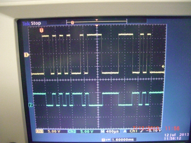
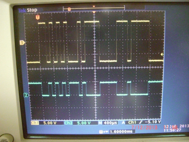
I did get the serial interface to work… sort of. I’m attaching my bit patterns for max (0xAA 0xE1 0x58) and min (0xAA 0xE1 0x22) extentions. The actuator extends beyond the end (and abruptly stops with an audible thump) with the max command and only withdraws partially with the min command. This is the similar response I had when I tried to send these commands with the Serial Transmitter program, though, so it sounds like I’m on the right track. At least the motor is responding to commands from my micro serial port. Now all I have to do is get the right values sent and received. I may try the Set Target High Resolution command to see if there’s any difference in response.
Thanks very much for sending the bit patterns for the commands. As it stands, the reason it didn’t work before was the ASCII formatting from a print() statement. I changed the outputs to putc() statements and it was correctly formatted. 
The byte string I use is the 4 byte high res goto position, 0XAA,0x(ID),0x40,0xYY(POSITION). Using just the high byte (up to 7F) is good enough for my needs and it made programming easy. 118 steps is enough resolution for me. I don’t go clear to the ends because if you do then you get a error flag because the motor disconnects with the limit switches. I did finally disable it but I just don’t go to the ends anyway.


