School Project

Hello all. I posted previously in the Robot Tech forum regarding a school project I’m working on. The thread is here if you’re interested.

Basically I need to make two resistance bend sensors linearly control two pairs of servos. I’m using the Pololu Baby-Orangutan B-168 and the Micro serial servo controller. I have everything wired up for the most part but I haven’t been able to figure out what command lines i need to use to declare the servo controller within the main body of the code. Below is the modified motor control sample code that I tried to incorporate servo commands into. I only have two servos declared for testing purposes. I know the code is wrong 100 different ways but it’s a start and I was hoping someone might be able to help.

Ultimately I’d want the servos in the first four ports on the servo controller and the serial (SIN) port would go to the PD1 port on the Baby-O. How do I declare that and do I need some other .h files other than the included orangutan one in all the sample codes?

#include <servotest/orangutan.h>


unsigned long prevMillis = 0;
unsigned char left, right;

left = servo_define(_SFR_IO_ADDR(DDRD), _SFR_IO_ADDR(PORTD), 6);
right = servo_define(_SFR_IO_ADDR(DDRD), _SFR_IO_ADDR(PORTD), 7);

int main()
{
  	servo_active(left); 	// Turn on left servo
	servo_active(right); 	// Turn on right servo
	servo_set(left, 1000);	// Center left servo
	servo_set(right, 1000); // Set right servo to max 

	while(1)
  {
    int bleft = analogRead(0);
	int bright = analogRead(1);
    
	int motorSpeed1 = bleft/2-256;  // turn pot reading into number between -256 and 255
	int motorSpeed2 = bright/2-256;	
	
	if(motorSpeed1 == -256)
		motorSpeed1 = -255; // 256 is out of range
    	servo_set(left, motorSpeed1);
  		
	if(motorSpeed2 == -256)
		motorSpeed2 = -255; // 256 is out of range
		servo_set(right, motorSpeed2); 		

  }
}

I understand that here the servos are declared in the PD6 and 7 ports, but do I declare the servo controller ports similarly?

Thanks in advance for any help.

Looks like you’re playing around with the sample servo control code from Orangutan-lib. That code is meant for generating PWM (Pulse-Width-Modulated) control signals for a couple of servos directly from the Orangutan, with no servo controller involved.

The serial servo controller generates these PWM control signals for you (which takes a lot of computing/timing load off of your Orangutan), and you command the servo controller with a digital serial interface, which is quite a bit different. It’s actually pretty simple to use once you get it set up. If you’re comfortable with the Orangutan-lib, you should take a look at the UART code (UART=Universal Asynchronous Receive/Transmit, AKA the serial port that transmits on PD1). You can send individual bytes to the servo controller using the uartSendByte() command. Alternatively, it takes very little code to configure the UART yourself, which might make your code a little smaller.

-Adam

I took a look at the online references and tried searching for some examples online and throughout the forum, but honestly I’m totally lost. I looked through the servo controller user guide online and noted the bit commands and what they were for, but I’m still not sure on placement or what the code should ultimately look like. I’ve seen a bunch of .uart samples for python and for other arduino (*spelling) controllers online but I’m still new to C programming and not sure what I’m looking at.

I know you helped me before on the wiring so you’re a little familiar with the project, (I really appreciate the help), if there is a site or someplace I might be able to find a general sample or layout other then the lib that would be easier for me to pick apart and learn that would greatly help. I don’t want to sound like I’m asking anyone to do the project for me, but I’m basically learning this all for the first time and need a little bit more help then most of the people on the forum.

again thanks in advance for any help.

The servo controller user guide will help you figure out what bytes to send, but not how to send them. Since the UART is a piece of hardware built into the AVR, the best thing to do to get an idea of how to use it is to skim the “USART0” section in the ATMega168 datasheet. I’m about to break one of my cardinal rules, and post code I just snipped together without actually testing on the target device (lets see if it comes back to bite me!).

#define F_CPU 20000000//Baby Orangutan CPU clock
#define BAUD 9600//baud rate for UART
#define MYUBRR 129//(F_CPU/16/BAUD-1)//baud rate variable for UART hardware

#include <avr/io.h>

void USART_Init(unsigned int ubrr){//Initialize USART hardware & settings for Serial Radio
   UBRR0H=(unsigned char)(ubrr>>8);//set buad rate
   UBRR0L=(unsigned char) ubrr;
   UCSR0B=(1<<TXEN0);//enable transmitter
   UCSR0C=(3<<UCSZ00);//Set frame format for 8bit with 1 stop
}

void USART_Trans (unsigned char data){//Transmit a byte of data over USART
   while(!(UCSR0A&(1<<UDRE0)));//wait for transmition to complete
   UDR0=data;
}

int main(){
   USART_Init(MYUBRR);//Initialize serial USART

   //MiniSSC-II Mode sample command
   USART_Trans(255);//start byte
   USART_Trans(0);//servo number
   USART_Trans(100);//position

   while(1);

   return 0;
}

This code should set up the UART for 9600bps serial communication, and send out the bytes {255,0,100}, which in MiniSSC-II mode (you will need to put on the mode selection jumper) should send servo 0 a little bit to one side of center (and after receiving the first byte, all of the other servos will automatically go to their center position). Once you verify that this works, you can do lots more by just setting up loops and variables, and using that same USART_Trans() function. Also, if you notice the code is almost directly copied out of the datasheet.

Good luck!

-Adam

Thanks a bunch I really appreciate it. I loaded it up in AVR studio and programmed it in. Unfortunately AVR studio is always asking me for a hex file and i wasn’t sure what to do, unless I’m misunderstanding a huge part of this. I used the motors1.hex and the analog1.hex from the examples I had previously downloaded. Unsurprisingly neither worked. I got a flashing red LED on the baby-o, with a solid green LED, and a solid yellow LED on the servo controller.

I tried plugging in the PORTD=0x00 That I’m using to send the data, but I wasn’t sure where it would go in the code you provided. Any advice?

Aah, yes, that’s an important part.

When you write code in AVRStudio you’re writing in C, and the compiler essentially translates your C code into AVR Assembler, the functional executable language of the AVR microcontrollers. This executable code is stored in a .hex file which is what you download to your Orangutan. So, if you have a project called MyProject, and you use the default settings, when you “build” your project it should create (or recreate) the file MyProject\Default\MyProject.hex. The AVRStudio program downloader will not automatically find the hex file from the open project, you have to find it through the “input hex file menu”.

Which programmer are you using? In any case, I strongly suggest you read through section 5A (and maybe 5B) of the Orangutan Programmer User’s Guide.

-Adam

Ok I’ve built the hex file, I should have remembered to Build the file, duh. using the current code i get the same result now with a solid red/green LED for the baby-o. and solid yellow for the servo controller. I tried inputting some pin code:

DDRD |= 1 << PD0;

PORTD |= 1 << PD0;

inside the while loop, but it threw some errors my way and I didn’t know what to do.

I currently have the servo controller “SIN” running to “PD0” on the baby-o, should I be using RS-232 and GND? Should I be using “OUT”?

Thanks.

The servo controller SIN pin needs to be connected to the Baby O’s PD1 pin for this code to work.

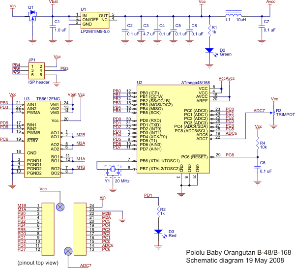
Take another look at the Baby O’s schematic:


If you look at the block representing the ATMega168, it lists the various I/0 pins on the chip, and their specialized secondary hardware functions in parentheses. PD1’s secondary function is (TXD), the Transmit pin of the chips hadware serial port (aka UART or USART). PD0’s secondary function is (RXD), which means it is the receive pin with that function.

The fact that the red LED came on is a good sign though. If you erase the code from the chip the red LED should go out. You can use it as a general indicator LED but it’s also tied to PD1, so when you configure PD1 to work as a serial transmit line it should come on. You may also be able to see it wink out ever so briefly as you send bytes of data out of the serial port. Don’t worry if you can’t though, it’s only really apparent if you’re sending lots of bytes in quick succession.

-Adam

Okay so changing form PDO to PD1 seemed to work for the most part. I managed to get some varying positions on the servo but nothing exact. Except the 100 setting seemed to center. I plugged in some of the analog bend sensor commands that I had used with the analog1 sample code. I didn’t totally understand the “start byte” number or where it came from (yet). But my biggest problem is that the code crashed and specifically wouldn’t recognize any of the analog command lines. Below is the code and the errors that I received. I’m sure it’s something simple, and I’ll keep at it for now.

On another note, I thought that to use the the micro servo controller with the pololu baby-o, it needed to be in “pololu” mode (without the jumper), and not in MSCII mode (with the jumper) which it seems to be working in.
Does this have to do with the USART commands?

    #define F_CPU 20000000//Baby Orangutan CPU clock
    #define BAUD 9600//baud rate for UART
    #define MYUBRR 129//(F_CPU/16/BAUD-1)//baud rate variable for UART hardware
  	
	#include <pololu/orangutan.h>
    #include <avr/io.h>
  

unsigned int sum;
unsigned int avg;
unsigned char samples;


int main()
{

  PORTC=0x00;
  set_analog_mode(MODE_8_BIT);
  sum = 0;
  samples = 0;
  avg = 0;
  start_analog_conversion(PORTC=0x00);  // start initial conversion

  while(1)
  {
    if (!analog_is_converting())     // if conversion is done...
    {
      sum += analog_conversion_result();  // get result
      start_analog_conversion(PORTC=0x00);          // and start next conversion
      if (++samples == 20)
      {
    
	avg = sum / 20;			// compute 20-sample average of ADC result
	            
    samples = 0;
    sum = 0;
      }
    }

    void USART_Init(unsigned int ubrr){//Initialize USART hardware & settings for Serial Radio
       UBRR0H=(unsigned char)(ubrr>>8);//set buad rate
       UBRR0L=(unsigned char) ubrr;
       UCSR0B=(1<<TXEN0);//enable transmitter
       UCSR0C=(3<<UCSZ00);//Set frame format for 8bit with 1 stop
    }

    void USART_Trans (unsigned char data){//Transmit a byte of data over USART
       while(!(UCSR0A&(1<<UDRE0)));//wait for transmition to complete
       UDR0=data;
    }

       USART_Init(MYUBRR);//Initialize serial USART

       //MiniSSC-II Mode sample command
       USART_Trans(avg+1);//start byte
       USART_Trans(0);//servo number
       USART_Trans(256-avg);//position

      
       return 0;
    }
}

Errors

Build started 23.3.2009 at 20:22:43

avr-gcc  -mmcu=atmega168 -Wall -gdwarf-2 -Os -std=gnu99 -funsigned-char -funsigned-bitfields -fpack-struct -fshort-enums -MD -MP -MT Bend_Servo_test.o -MF dep/Bend_Servo_test.o.d  -c  ../Bend_Servo_test.c

avr-gcc -mmcu=atmega168 -Wl,-Map=Bend_Servo_test.map Bend_Servo_test.o     -o Bend_Servo_test.elf

Bend_Servo_test.o: In function `main':

C:\.../Bend_Servo_test.c:18: undefined reference to `set_analog_mode'

C:\.../Bend_Servo_test.c:22: undefined reference to `start_analog_conversion'

C:\.../Bend_Servo_test.c:26: undefined reference to `analog_is_converting'

C:\.../Bend_Servo_test.c:28: undefined reference to `analog_conversion_result'

C:\.../Bend_Servo_test.c:29: undefined reference to `start_analog_conversion'

make: *** [Bend_Servo_test.elf] Error 1

Build failed with 5 errors and 0 warnings...

Yay progress!

It looks like you followed these instructions for adding the Pololu AVR libraries to the WinAVR include directories (if not go ahead and do it now), but you probably missed these instructions at the end of all the example programs, which tell how to configure your own AVR Studio project to include the Pololu libraries. With the libraries added to the link list, your code compiles for me. Also, It looks like it could work as written, but normally you define functions outside of your main loop, like this:

#define F_CPU 20000000//Baby Orangutan CPU clock
#define BAUD 9600//baud rate for UART
#define MYUBRR 129//(F_CPU/16/BAUD-1)//baud rate variable for UART hardware

#include <pololu/orangutan.h>
#include <avr/io.h>


unsigned int sum;
unsigned int avg;
unsigned char samples;


void USART_Init(unsigned int ubrr){//Initialize USART hardware & settings for Serial Radio
	UBRR0H=(unsigned char)(ubrr>>8);//set buad rate
	UBRR0L=(unsigned char) ubrr;
	UCSR0B=(1<<TXEN0);//enable transmitter
	UCSR0C=(3<<UCSZ00);//Set frame format for 8bit with 1 stop
}

void USART_Trans (unsigned char data){//Transmit a byte of data over USART
	while(!(UCSR0A&(1<<UDRE0)));//wait for transmition to complete
	UDR0=data;
}

int main()
{
	PORTC=0x00;
	set_analog_mode(MODE_8_BIT);
	sum = 0;
	samples = 0;
	avg = 0;
	start_analog_conversion(PORTC=0x00);  // start initial conversion

	while(1)
	{
		if (!analog_is_converting())     // if conversion is done...
		{
			sum += analog_conversion_result();  // get result
			start_analog_conversion(PORTC=0x00);          // and start next conversion
			if (++samples == 20)
			{

				avg = sum / 20;         // compute 20-sample average of ADC result

				samples = 0;
				sum = 0;
			}
		}

		USART_Init(MYUBRR);//Initialize serial USART

		//MiniSSC-II Mode sample command
		USART_Trans(avg+1);//start byte
		USART_Trans(0);//servo number
		USART_Trans(256-avg);//position


		return 0;
	}
}

I was surprised that the code compiled at all with the USART functions written inside the main function, you learn something new every day!

As to your question about the servo controller modes, UART serial is just a communication standard, a set of protocols for transmitting information. You can think about UART serial ports like telephones, if they’re set up and connected properly you can call any telephone in the world from any other telephone and talk to someone on the other end of the line. Rather than sounds though, you’re transmitting 8-bit numbers (values from 0 to 255). Pololu mode and MiniSSC-II mode on the servo controller are more like spoken languages. You can call anyone in the world and make a proper telephone connection, but if you and they aren’t speaking the same language on the phone you won’t understand each other.

MiniSSC-II mode is just a simple language that consists of three byte commands (like three number sentences). The first byte is a start byte, which must always be 255. The next byte is the servo number, in your case from 0 to 7. The third byte is the position you want to set that servo to, from 0 to 254 (255 isn’t a valid position, since only start bytes are allowed to be 255). That’s the grammar of the MiniSSC-II mode language. You have to stick to it strictly, three byte sets with 255 as the first byte, or your servo controller will get confused.

“Pololu” mode on your servo controller is a significantly more complicated language, but it lets you use more advanced commands (higher positioning resolution, speed control, and such). It’s also a little more flexable in terms of letting you talk to other Pololu devices (more servo controllers, motor controllers, etc) on the same serial lines without getting confused. For now I would suggest sticking with MiniSSC-II mode; it’s much simpler and more than sufficient for most applications (for example, this was all done with MiniSSC-II servo controllers).

-Adam

Thanks, that fixed the errors. only my code didn’t work :frowning: I’ll get around to playing with it. I had some other problems with the servo controller when it came to renaming the servo numbers from 0-7 to 8-15. I did this so that I could unlock the 180 degree range of the servo in MCSS mode. With the code you sent me I managed to get the servo to run the full 90 degrees. I used the provided code from the manual:

      USART_Trans(128);//start byte
      USART_Trans(2);//servo number
      USART_Trans(1);//position

I ran it and it seemed to go well, the green led blinked a bunch in two flash intervals, etc etc. But when I ran the code with the servo number as 8 instead of 0, I couldn’t get the servo to leave the neutral position. Any thoughts on what I might have missed?

In MiniSSC-II mode your servos are probably responding to numbers 16-31. You don’t have to reprogram the servo numbers to get access to the wider range settings.

In MiniSSC-II mode by default, you can get 90 degree motion in out of your servos by addressing them as 0-7, and get 180 degree motion out the same servos by addressing them as 8-15. So if you want to to move servo 0 through a wider range of motion, you just use address 8. By bumping the address set up by 1 you moved the 90 degree range addresses up to 16-23, and the 180 range addresses up to 24-31!

In general you only need to reprogram numbers on Polou controllers if you want to daisy-chain several together on one serial line and address them separately. You can continue to use the servo controller with the new addresses, or program it back to the default addresses, your choice.

-Adam

Okay. So I finally got some progress going on. I can call all the 90 degree angles and most in range for 180 degrees. i cant go from 0-254, only 33-220, for some reason.

more importantly. just now after switching out the batteries I had some fatal problems. I didnt mess with anything but switching the battery and now I get a blinking GREEN LED and a solid RED LED on the servo controller, which suggests the braud rate too high. And NO LEDS on the Baby-O. There is a dim red LED that blinks randomly when I jiggle the PD1 connection.

Is it dead?

I get the error message in AVR Studio for setting the ISP frequency and checking the CKDIV fuse or CLKPR setting. I dont really know what the hell to do.

Now I get a solid yeloow and a blinking red on the servo controller.

Well the good news is that the servo behavior you’re describing isn’t abnormal. Servos can only turn so far, so you’re probably just hitting the mechanical limits of your particular servo model. This isn’t immediately problematic, but it will wear out the servo over time, so it’s good to avoid pressing against the stops regularly.

Yikes, sounds like trouble with the Baby O. Can you try disconnecting everything from the Baby Orangutan, then reconnecting power? If not even the green power LED is coming on (which is essentially just dumb bulb which doesn’t require any of the digital electronics to be working) then it’s really broken. Is it possible that a loose wire brushed against the board and made a connection between two exposed points that shouldn’t be connected?

It could just be that you blew out the voltage regulator, but that’s really hard to do without hooking up power and ground backwards, and the Baby Orangutan has reverse polarity protection, which works really well. I’ve abused them a bunch and never had this happen. The servo controller on the other hand, does not have the same protection, and I’ve fried a couple of those!

Definitely don’t try to program the Baby O any more unless you at least see that light come back on. In any case, if you still don’t see even the green LED come on with just the battery pack and nothing else connected to the Baby O it’s probably time to send it back to Pololu. They have a very nice repair policy, but you should get in contact with them right away to minimize your down time.

Sorry to be the bearer of bad news.

-Adam

I went ahead an ordered one more of each, since I don’t have any back ups. :frowning: I was wondering if using Pololu mode for the servo controller would yield better control for what I’m doing. I could only find some adruino sample code and I keep getting errors just compiling it. any thoughts?

Are you talking about the code given in this thread? You should be able to copy the functions directly, just change the Serial.print(X,BYTE) commands to USART_Trans(X), like this:

void put(unsigned char servo, unsigned int angle){
   //servo is the servo number (typically 0-7)
   //angle is the absolute position from 500 to 5500

   //Send a Pololu Protocol command
   USART_Trans(0x80); //start byte
   USART_Trans(0x01); //device id
   USART_Trans(0x04); //command number
   USART_Trans(servo); //servo number
   //Convert the angle data into two 7-bit bytes
   USART_Trans(((angle>>7)&0x3f)); //data1
   USART_Trans((angle&0x7f)); //data2
}

void servoOff(unsigned char servo){//turns off a servo
   //(servo will go limp until next position command)
   //servo is the servo number (typically 0-7)

   //Send a Pololu Protocol command
   USART_Trans(0x80);//start byte
   USART_Trans(0x01);//device id
   USART_Trans(0x00);//command number
   USART_Trans(servo);//servo number
   USART_Trans(0x0f);//data1 (turn servo off, keep full range)
}

void servoSetSpeed(unsigned char servo, unsigned char speedcmd){
   //servo is the servo number (typically 0-7)
   //speed is servo speed (1=slowest, 127=fastest)
   //set speed to zero to turn off speed limiting
   
   speedcmd=speedcmd&0x7f;//take only lower 7 bits of the speed
   
   //Send a Pololu Protocol command
   USART_Trans(0x80);//start byte
   USART_Trans(0x01);//device id
   USART_Trans(0x01);//command number
   USART_Trans(servo);//servo number
   USART_Trans(speedcmd);//data1
}

Once again, I’m completely breaking my own rule about not posting untested code, so let me know if you need to tweak this at all to make it work. To call these functions you’ll either need to paste them into your code above the main function (the easy way), or create prottypes of the functions themselves. If you still get errors feel free to post them (and the complete code that’s causing them).

Have you tried connecting power and nothing else to your Orangutan? Also, do you have a multimeter you can check the voltage between the VCC pin and GND with?

-Adam

Okay, well it didn’t crash on me and I returned only 1 warning. “…/pololuservo.c:23: warning: implicit declaration of function ‘USART_Trans’” this USART_Trans function appears right after the command to turn the servo off. but other then that it compiled nicely. I haven’t contacted Pololu yet regarding the baby-o, although I will soon, But I went ahead and order two more just in case since it’s crunch time and I can’t afford to wait. They should be here Monday.

Since I can’t run the code to see what it does, I tried something new and it still managed to compile without any errors and I wanted to know if it would indeed work.

void servoSetSpeed(unsigned char servo, unsigned char speedcmd){
       //servo is the servo number (typically 0-7)
       //speed is servo speed (1=slowest, 127=fastest)
       //set speed to zero to turn off speed limiting
       
       speedcmd=speedcmd&0x7f;//take only lower 7 bits of the speed
       
       //Send a Pololu Protocol command
       USART_Trans(0x80);//start byte
       USART_Trans(0x01);//device id
       USART_Trans(0x01);//command number
       USART_Trans(servo);//servo number
       USART_Trans(speedcmd);//data1

last two lines become:

void servoSetSpeed(unsigned char servo, unsigned char speedcmd){
       //servo is the servo number (typically 0-7)
       //speed is servo speed (1=slowest, 127=fastest)
       //set speed to zero to turn off speed limiting
       
       speedcmd=speedcmd&0x7f;//take only lower 7 bits of the speed
       
       //Send a Pololu Protocol command
       USART_Trans(0x80);//start byte
       USART_Trans(0x01);//device id
       USART_Trans(0x01);//command number
       USART_Trans(0x00 && 0x01);//servo number
       USART_Trans(0x7F);//data1

Will it apply my settings to both servos or just the one?

Also I had access to a multimeter on campus, but I wont be on campus till the new babies get here, I do have one of those tools with the fuse to check if the power is on. the name escapes me at the moment, but I’ll see what happens when i use it.

For the “Implicit Declaration” warning, it sounds like you need to move the USART_Trans function up above your main function like I mentioned before. C is compiled from top to bottom, so you need to explain what a function does before you try to use it. Some compilers let you skimp on that rule a little, as it sounds like WinAVR is willing to let you do (since it’s a warning and not an error) but it’s a good practice to follow.

Unfortunately what you did to the servoSetSpeed command won’t work. “&&” is the logical and operator, so (0x00&&0x01) is like saying (False&&True), which is false, so the compiler will evaluate the statement as (FALSE), which is numerical (0). So essentially the function as you have it written will set servo 0 to speed 0x7F. The Pololu protocol doesn’t support setting the speed of multiple servos at one time anyway. The right way to set the speed of both servos 0 and 1 to 0x7F would be to paste the original function above your main function, then call it twice from within your main function, like this:

servoSetSpeed(0,0x7F);
servoSetSpeed(1,0x7F);

Aside from that 0x7F is the fastest speed setting aside from no speed setting at all, so you probably won’t even notice a perceptible speed change. With no speed control turned on, the servos move as fast as they possibly can already. Pololu speed control staggers the changing position signal, rather than changing it all at once. This lets you slow down the servo motion smoothly, but you can’t make the servos move any faster than they did with no speed control. It would probably make more sense to call it speed limiting.

-Adam

I checked the bay-o and power is going to the VIN and GND pins but not to the VCC pin, or anywhere else on the board. I’m assuming its dead at this point. Also I took your advice and moved some stuff around. Also, can I call command 4 (absolute position) the same way I can call SetServoSpeed within the main loop? below is yet another sample of what I mean. It compiled without any errors but again it begs the question. “but will it work?” I suppose I’ll find out Monday.

    #define F_CPU 20000000//Baby Orangutan CPU clock
    #define BAUD 9600//baud rate for UART
    #define MYUBRR 129//(F_CPU/16/BAUD-1)//baud rate variable for UART hardware

    #include <pololu/orangutan.h>
    #include <avr/io.h>


    void USART_Init(unsigned int ubrr){//Initialize USART hardware & settings for Serial Radio
       UBRR0H=(unsigned char)(ubrr>>8);//set buad rate
       UBRR0L=(unsigned char) ubrr;
       UCSR0B=(1<<TXEN0);//enable transmitter
       UCSR0C=(3<<UCSZ00);//Set frame format for 8bit with 1 stop
    }

  
    void USART_Trans (unsigned char data){//Transmit a byte of data over USART
       while(!(UCSR0A&(1<<UDRE0)));//wait for transmition to complete
       UDR0=data;
	}
	
	
	void put(unsigned char servo, unsigned int angle){
       //servo is the servo number (typically 0-7)
       //angle is the absolute position from 500 to 5500

       //Send a Pololu Protocol command
       USART_Trans(0x80); //start byte
       USART_Trans(0x01); //device id
       USART_Trans(0x04); //command number
       USART_Trans(servo); //servo number
       //Convert the angle data into two 7-bit bytes
       USART_Trans(((angle>>7)&0x3f)); //data1
       USART_Trans((angle&0x7f)); //data2
    }


    void servoOff(unsigned char servo){//turns off a servo
       //(servo will go limp until next position command)
       //servo is the servo number (typically 0-7)

       //Send a Pololu Protocol command
       USART_Trans(0x80);//start byte
       USART_Trans(0x01);//device id
       USART_Trans(0x00);//command number
       USART_Trans(servo);//servo number
       USART_Trans(0x0f);//data1 (turn servo off, keep full range)
    }

    void servoSetSpeed(unsigned char servo, unsigned char speedcmd){
       //servo is the servo number (typically 0-7)
       //speed is servo speed (1=slowest, 127=fastest)
       //set speed to zero to turn off speed limiting
       
       speedcmd=speedcmd&0x7f;//take only lower 7 bits of the speed
       
       //Send a Pololu Protocol command
       USART_Trans(0x80);//start byte
       USART_Trans(0x01);//device id
       USART_Trans(0x01);//command number
       USART_Trans(servo);//servo number
       USART_Trans(speedcmd);//data1
    
		}
	int main()
{

	servoSetSpeed(0,0x00);
	servoSetSpeed(1,0x00);

	put(0, 500);
	put(1, 500);

	delay(100);
	
	put(0, 1000);
	put(1, 1000);

}

The numbers are completely arbitrary. I just wanted to see if it would compile.

It sounds like the MOSFET (reverse battery protection) on your Baby Orangutan has burned out. I’m sure you connected the battery the right way, but the normal operating maximum input voltage for the Baby O is 13.5V, with an absolute maximum (can hand it for a little while, but not forever) of 15V. Your 12V NiMH battery pack is probably up at around 14.5V fully charged, but more if it’s fresh off the charger. When the problems started had you just taken the battery pack right off of the charger?

If you want to keep using the same battery pack you should let it cool for a while before using it, or maybe even drain it a little first. Even better, since you’re not hurting for space, get a bigger regulator to put between the battery pack and the Baby O. I don’t mean a big one like what you’re using for your servos, but a little (~$1) linear regulator that would drop the voltage down to the normal range for the Baby O.

You could probably even resurrect your current Orangutan with one of these guys from Radio Shack. It can handle up to 35V input! It should identify which pin is which on the packaging, but it should have an input pin, which you would connect the battery power line to, a GND pin which you connect to the battery ground to (GND should also still be connected to the Orangutan), and an output pin, which you would connect to your broken Orangutan’s VCC pin (you would connect this to the VIN pin of a normal working Orangutan). This will bypass the board’s built-in regulator, so if you do try this, make sure you have everything wired right first!

As for your code, you need to make sure to have the line “USART_Init(MYUBRR);” somewhere in your main function before you call any of the servo controller command functions, to turn on and configure the serial port. Aside from that and the arbitrary numbers (a put position of 500 is almost definitely going to slam your servo into the stops, and set_speed(0x00) isn’t going to change the speed of the servos at all) your code looks good. That’s exactly how you’re supposed to use functions. That way your main function is nice and compact, and you can understand what its doing just by looking at it.

There is one more thing you should do to make this run properly on a microcontroller. On personal computers, when a program reaches the end of its code it returns back to the operating system. The microcontroller on your Baby Orangutan doesn’t have an operating system as such, so when it reaches the end of the code it loops back to the beginning and starts over. So immediately after the second pair of put commands in your code, your Baby O will loop back around to the beginning of the main function, and send out the two speed commands and the first two put commands again. In general, if you don’t already have a loop that runs forever in the main function of your microcontroller program, you want to end the main function with the line “while(1);”. That way the microcontroller will just sit there when it’s done, instead of looping the whole code over again and again.

-Adam