School Project

Hi all, I hope this is the right section ((please move it if it isn’t))

I’m an engineering student in his senior year and like most students, I wasn’t taught anything practical. Cutting to the chase, I need help, partly because I get differing opinions on the subject, but mostly because I am inept.

I need to setup and program two bend sensors to control three servos (two will work in parallel running the same code). I bought the Baby-O and the servo controller. I have the bend sensors and the servos. I also was hoping to run the entire thing off one 12V 1600mA battery. Below (if it uploads) is the primitive neanderthal schematic that I have done in MsPaint to illustrate how I believe it needs to be setup. I need help in confirming whether this is right or not. If it’s not right, I could really use some advice, because I’m not really confident in this area.

Sorry I should have added some more information.
Its the baby-O 168
Micro servo controller
hobbico 333oz-in servos
bend sensor 20-50kOhm range
12V 1600mA battery

Also I considered adding an inline 6V regulator between the servo and the controller for each servo. and finally an LED battery life gauge that plugs into the baby-O. It’s not a must have, but if I can get it to work then why not.

Hey Jackel,

I feel your pain. A lot of core engineering curriculum isn’t applicable in the real world by itself. That why it’s always good to fool around with actual, physical projects, like you’re doing now! I’m a little confused though, do you mean you’re building two identical systems each consisting of one bend sensor, one Baby O, one servo controller, and one servo? Where does the third servo go?

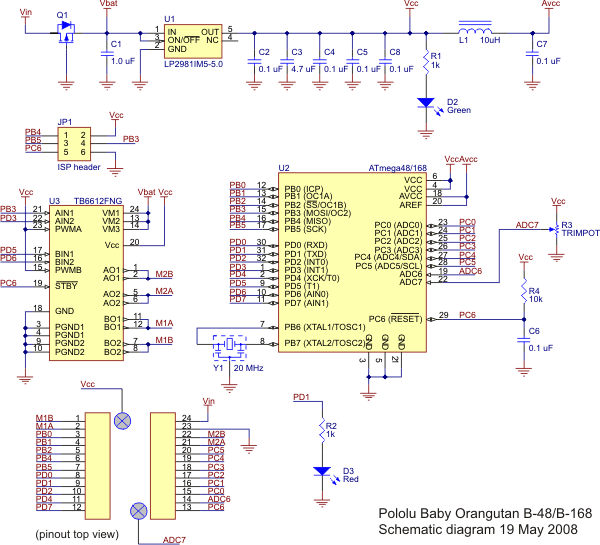
Can you give some more specifics about (or just the model of) your bend sensor? I’m guessing it has an analog output, which means it will need to be connected to one of the analog input pins. Lets take a look at the Baby Orangutan schematic from the user’s guide:

Pin names and function abbreviations are shown on the ATMega168 box in the schematic, and you need to pick an ADC pin (Analog to Digital Converter). The ADC6 pin would be a good choice, as it does nothing but analog input, but any of the PORTC pins (named PC#) will also work. Depending on the sensor you may also need to pair it with a resistor, but since you show it with three leads I’m assuming it is set up as a voltage divider already.

Serial bytes are just timed high/low pulses, so you can generate them in software on any I/O pin you like, but the ATMega168 microcontroller also has built in serial hardware, called a USART (Universal Synchronous and Asynchronous Serial Receiver and Transmitter) which makes things much simpler. Essentially in your code you will be able to say “transmit this” rather than “I want to transmit this, so bring this pin high, pause for this long, then bring it low, then pause for this long, then etc…”. The transmit pin (TXD) for the USART is PD1, so you’ll want to connect that to SIN on your servo controller.

Can you tell me more about your battery pack? You can find cheap little LED power bar things for most battery types. The Baby O and the servo controller can take 12V, but that would probably damage the servos, which are only designed to run between 4V and 6V. The servos have a separate power bus, so you can run them off of a 6V battery pack. Actually, you can run everything off of a 6V battery pack if you like, are you stuck with the 12V pack? Servo motors take a lot of current, so powering them through regulators isn’t a great idea, but it can be done, especially if the servo won’t be working hard (i.e. stalling).

Finally, did you happen to also pick up an AVR programmer, like this one from Pololu or this one from ATmel perhaps? You’ll need one to download programs to your Baby O. It’s one of those things you have to buy once, but then you can use it forever.

-Adam

P.S. While a separate servo controller makes things easier, you can generate servo control signals directly from the Baby O. It gets complicated when you want to control many servos, but it’s not too bad for just one or two.

Hey thanks for the help .

I’m running one system with two bend sensors and three servos in total. 2 of the servos will be connected to one bend sensor. I just did the crappy schematic with one of each. All three servos would be on the servo controller and the bend sensors would be on the baby-o. ideally.

I found and ordered the bend sensors from Images Scientific Instruments Bi-Directional Flexible Bend Sensors - FLX-01. It only came with two unmarked black leads. I was told one goes to ground and the other gets split to power and signal. Do I have hat right?

I bought this battery from Lynxmotion. I also bought the LED power bar from the same website.

I did get the Pololu USB AVR programmer, I have a copy of WinAVR, AVR Studio4 and Dev-C++ installed. …and shamefully a copy of “C for Dummies.”

As to the power situation, a 5-cell NiMH battery pack would be a better choice. You can power everything from it directly with no regulators or worries. Is it too late to return your battery pack? Or, if you want you can actually break your 10-cell pack apart and turn it into two separate 5-cell packs, and its always nice to have a spare. Radio Shack sells replacement connectors for a couple of bucks.

The problem you’ll run into there is if your battery charger is specific to the battery voltage. I see that LynxMotion’s only 12V charger is a smart charger that works with a range of battery voltages. They seem to claim it will work with 5-cell (6V) packs, but in the picture the charger says 7.2V-12V. I would go by whatever the charger says on it. If it does say 7.2V it will still charge up a 6-cell pack, but it might not stop trying to charge when the pack is full, which would heat it up and shorten it’s lifespan. In any case I would keep it on the lower current setting unless you’re in a serious hurry. This is all assuming this is even the charger you have.

Alternatively you could put a big beefy regulator like this one in between your 12V battery pack and the servo power lines. This bad boy can source a continuous 10A, so really you only need one, not one per servo.

You will need to put a resistor in line with your bend sensor (VCC to Resistor to Bend Sensor to Gnd, or VCC to Bend Sensor to Resistor to Gnd), and run a wire from the point between the resistor and the bend sensor to your ADC input pin. The size of that resistor depends on the resistance of your bend sensors, and how much that changes as they bend. I see there are a couple of models listed, but they also have large resistance ranges. Can you measure the neutral and flexed resistance of your sensors with a multimeter?

It sounds like you’re in good shape. With three servos it will make things simpler to use the serial servo controller, so good call there.

-Adam

P.S. And there’s nothing shameful about C++ for dummies.

I bought this charger. I actually haven’t used it yet. And I had bought two of these 6-Volt Regulators. I suspected I might need a third, if placing them between the controller and the servo, rather then between the battery and the controller, like I had originally thought. The description for the bend sensor was: “FLX-01-M Medium resistance range, nominal resistance between 20K - 50K” I bought some 10kOhm resistors for it just in case, but I realize that might be a bit excessive. I was hoping to run the entire thing off one battery source if possible, also the there is a project requirement of 45-60 minute run time for the system. Of course maximizing the time as close to 60 minutes as possible would be ideal.

I will post an updated schematic when I get the chance.

Thanks for the ongoing help.

Out of curiosity, does the charger you got in the mail say “For 7.2-12V…”, like the one in the picture on the LynxMotion website, or does it say “For 6.0 - 12V…” like the product description?

The regulator you bought can handle current for three servos, but it has a maximum input rating of 8.4V, so hooking it up to a 12V battery pack is not a good idea. You can still build your system with only the parts you have already though.

Assuming your charger won’t go lower than 7.2V like the one in the picture, it will work with NiMH packs with between 6 and 10 cells. A six cell pack will have a freshly charged voltage of about 8.6V, which is only slightly over the rating of your regulator, and it will drop very quickly, even just as the pack cools off after charging. You can cut the shrink wrap off of your battery pack, remove four of the cells from one end of the series, then solder the wire lead to the metal tab on the last remaining cell. You can then charge this pack with the charger you already have, power the servo controller and the Baby O with it, and power the servos through the regulator. You can probably even use the same LED battery meter by changing the dip-switch settings.

The interesting thing about batteries in series in this case is that you won’t actually be decreasing the runtime of your system by removing cells from the pack. The servo controller electronics and the Baby Orangutan both have linear voltage regulators, and I’m pretty sure that’s whats under the shrink-wrap of your servo power regulator as well. These simple and inexpensive regulators burn off extra power as waste heat to drop the voltage to your desired level. If you reduce the input voltage by removing cells from the pack, you’re also decreasing the amount of energy that will be wasted as heat. Your battery pack is has a 1600mAh (milli-amp-hours) rating, meaning you can draw 1.6 amps from it at 12V for one hour (in reality it won’t be quite that good, but it’s a place to start). This also means you can draw 1.6 amps at ~1.2V from each cell for an hour after a full charge. So, if your whole system draws less than 1.6A average, you should be in good shape.

Also, you can go through a lot of math to figure out the best resistor value to maximize your measurement resolution, but how many different positions do you really need to be able to measure? 10K is probably a good choice, or you might want to put a couple in series. Do you have a volt-meter around you can use to measure the actual range of resistances (straight to fully bent) you get from your bend sensor?

-Adam

The charger is rated between 6-12 V (auto detecting, and can has charge setting 0.9A or 1.8A for output current. The dip switches range for 4-5-6-7 cell batteries. between 4.8, 6, 7.2, and 8.4 V. I thought I could use the 5 cell 6V setting, plug it into the baby-o and run code to scale it for the meter. But I think that logic proves how much I don’t know about electronics. cutting down the number of cells will lighten the battery up a bit, (always a good thing) but how much heat dissipation are we talking? a lot I would imagine. I do have access to a multimeter. I took measurements with just the bend sensor plugged in and read the following values:

0 degrees = 15-20 kOhm (no bend)
10-15 degrees = 10 kOhm
25-30 degrees = 7 kOhm
45 degrees = 2.5-3.2 kOhm
90 degrees = 1.0-2.5 kOhm
180 degrees = 0.7-1.5 kOhm.

the degree ranges are not exact, and the resistance ranges reflect that of both the +ive and -ive directions of the bend sensor.

I probably only need to read 24 positions, give or take. I need the servo(s) to be linearly related to the bend sensor position and timing. the sensor is going into a glove so I need to assess which ranges need to be used. The associated range of the servo is also yet to be determined. I know it wont be a simple as: 0 degree bend=0 degrees of rotation etc. But I figure once I get things wired, I can learn and play with the code until I can get it to work.

I’m going to post some real pictures and update the schematic.

This is again with one servo and one bend sensor
I imagine that each bend sensor signal goes to ADC6 & 7
each servo gets its own plug in the controller. The green squiggle is a resistor.
The thing between the servo and the controller is an unsheathed voltage regulator. (I ripped off the cover out of curiosity the day i got it.)

Is this getting closer to “not blowing up” status?

Well, that wouldn’t blow up, but it wouldn’t quite work either.

The servo controller board has separate pins for servo power from the rest of the servo controller board, so you’ll need to connect power to them (this would be an easy place to put the regulator). And PD1 is the Baby Orangutan’s serial transmit pin. The ADC7 pin already has a little trim-potentiometer connected to it (for testing ADC functions), so you’ll have to run one of your bend sensors to one of the PC# pins. ADC6 is fine though. Also, you need to switch up the bend sensor/resistor order a little.

A picture us worth a thousand words, so, your final setup would look something more like this:


Go go MS paint!

You still have the issue with the battery pack being higher-voltage than the regulator is designed for. If you don’t want to remove cells from the pack you could see how well the regulator does with the full battery power (keep in mind that with a full charge that pack will output 14.5V, 72% out of spec!). It might be able to take it for a while, but on the other hand what happens to your grade if the regulator explodes in the middle of your final demonstration?

-Adam

P.S. I once blew out a regulator in the middle of a poster session. It was loud. Fortunately it was only powering a camera on a robot, not the robot itself, so we still had something to demonstrate.

Thanks. The operating instructions for the regulator says it does 10W of power dissipation. It doesn’t specifically state there is a limit, but I know you’re right. Also, the regulator has a set of three header pin leads coming from each end. (-+s) can I ignore the signal lead coming from it when connecting it from the battery to the board? I had originally taken the cover off of it to see if the signal bypassed anything but I couldn’t tell. Also the gauge on my battery is like 10-12 gauge, will I cause a lot of grief if I use a 14 gauge wire to slice the line, then cut down to whatever gauge the regulator is, (16g)?

Also would I be able to solder a jumper to the vcc=vs leads on the servo controller to run the controller off the servo power (which is run off the battery now)?

Cutting down the battery to 5-6 cells would be better/safer/lighter.

Thanks again. looking forward to finalizing a working prototype.

The LynxMotion product web page for your regulator says “Current is 10 amp cont. 20 amp peak at 7.2vdc in. 8.4vdc max input.” You’re not going anywhere near 10A, and I have no problem with pushing components beyond their stated limits to find their real limits, but you can’t always rely on something like that not breaking at an important time. You might try hooking up your unmodified battery pack to it and moving three servos around with its power. If it gets hot but still touchable, it’ll probably be okay. If it gets so hot you have to pull your finger away, it’s probably about to destroy itself.

I would guess the signal wire just goes straight through from one connector to the other, to make it easier to put this regulator in-line with a servo or other RC signal device. And no, you won’t cause any grief using those smaller wires. Battery packs have huge leads in case you’re going to draw like 50 amps from them, but your servos and the regulator do just fine with 20 or 22 gauge wire.

I would stay away from the VCC=VS pins for now. The VIN pin on the servo controller can handle up to 16V because it goes to a small 5V regulator which powers the signal generating chip. The VCC=VS jumper connects the servo power line DIRECTLY to the signal generating chip, without going through the regulator. Two common mistakes people (myself included) make when they connect the VCC=VS pins are:

  1. Connecting power just to the VIN pin, and trying to power the servos with the 5V generated by the on-board regulator: This regulator is very tiny, and only capable of sourcing a few milliamps. Nothing will get hurt this way, but when you try to move a servo the power drain will reset the board.

  2. Connecting power in excess of 5.5V to the servo power lines: Servos are pretty hefty. They’re rated for 6V, but you can usually get away with higher voltages some of the time (running them off of a fully charged battery pack up in the 7V-8V range for example). The signal generating chip is only rated for up to 5.5V though, with an “absolute maximum” rating of 6.5V. This means that above 5.5V, the chip will burn out eventually, and at or above 6.5V the chip could burn out immediately. Also, DC motors (like servos) generate a lot of electronic noise on their power lines, which can cause problems for the signal generating chip. Even if you only have one battery, I would recommend splitting it to the servo power pins and the VIN pin, since the regulator will help to suppress this noise.

So, the safe ways to connect power to your servo controller are:

It’s not explained well in the documentation, and it fooled me for a while. Keep in mind that in the top configuration, those two batteries could just be one with the wires split off.

-Adam

Thanks a bunch for all the help. I started soldering all the necessary wiring, I’m trying to do this as cleanly as possible so I don’t have to do it twice. Once this is all said and done and hooked up, coding will be my next hurdle. Hopefully I’ll have a better understanding of it by then.

Thanks for all the help, hopefully I don’t screw it up too bad. I’ll keep an eye on the regulator and the heat dissipation.