Repeated Motor Driver Failures (Pololu 24v21) – Overheating, Back-EMF Protection, and Current Limiting Questions

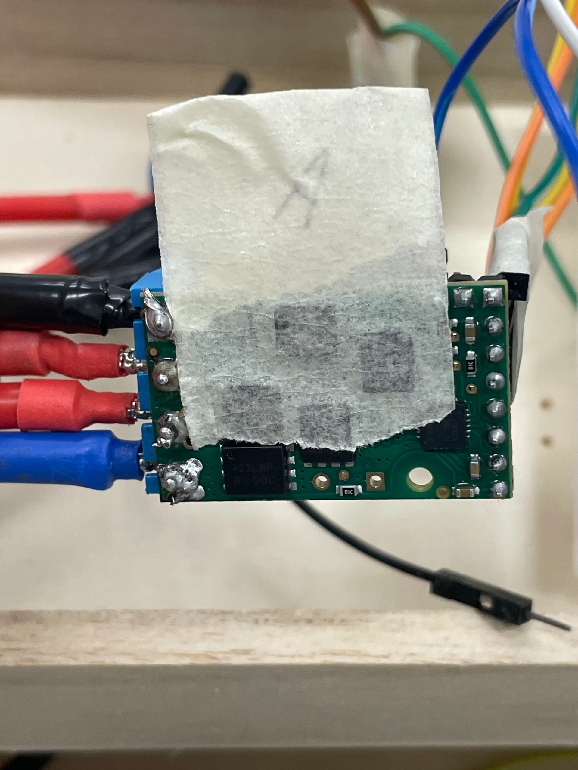
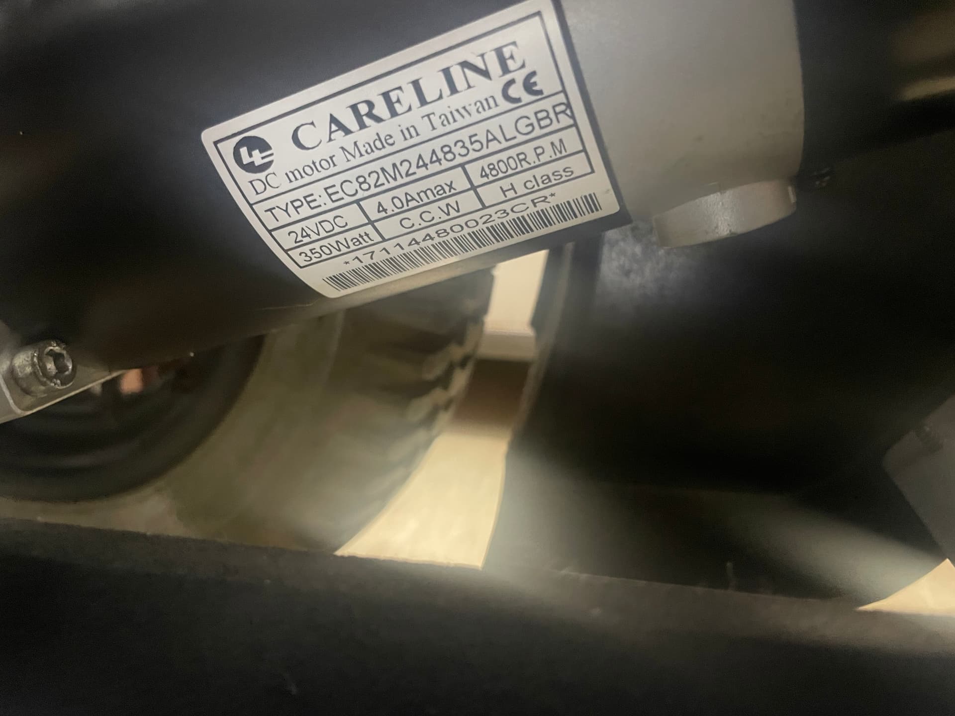
Hello, I’m using a polu24v21 product. I already have 4 broken motor drives… So… I’m writing to ask for advice. I bought this motor drive to run 2 wheelchair motors (24v 350W per each). I have one motor drive in each motor and the motor and battery lines are 12AWG thick wires.

Sometimes motor drives show signs of overheating. (It’s too hot to hold when you touch it with your hands.) I think the cause of the failure is overheating, and there are two causes of overheating.

  1. Back electromotive force generated during sudden motor shutdown

I would like to add capacitors and resistors to resolve this.

1.1 Circuit and Parts Specification to Connect
I purchased capacitors (470µF 105℃ 50V) and cement resistance (10Ω 10W) to solve this.
This is because I thought that if the motor suddenly stopped and back electromotive force was generated, the capacitor attached to the motor drive might be insufficient.
I also wanted to release heat through cement resistance.
So I want to connect two capacitors in parallel and connect the resistors. (two capacitors in parallel)-(cement resistance)
Will this motor drive fit the capacitors and resistance specifications it can handle? Would 2 parallels be too much? Or would it be burdensome to connect this circuit?

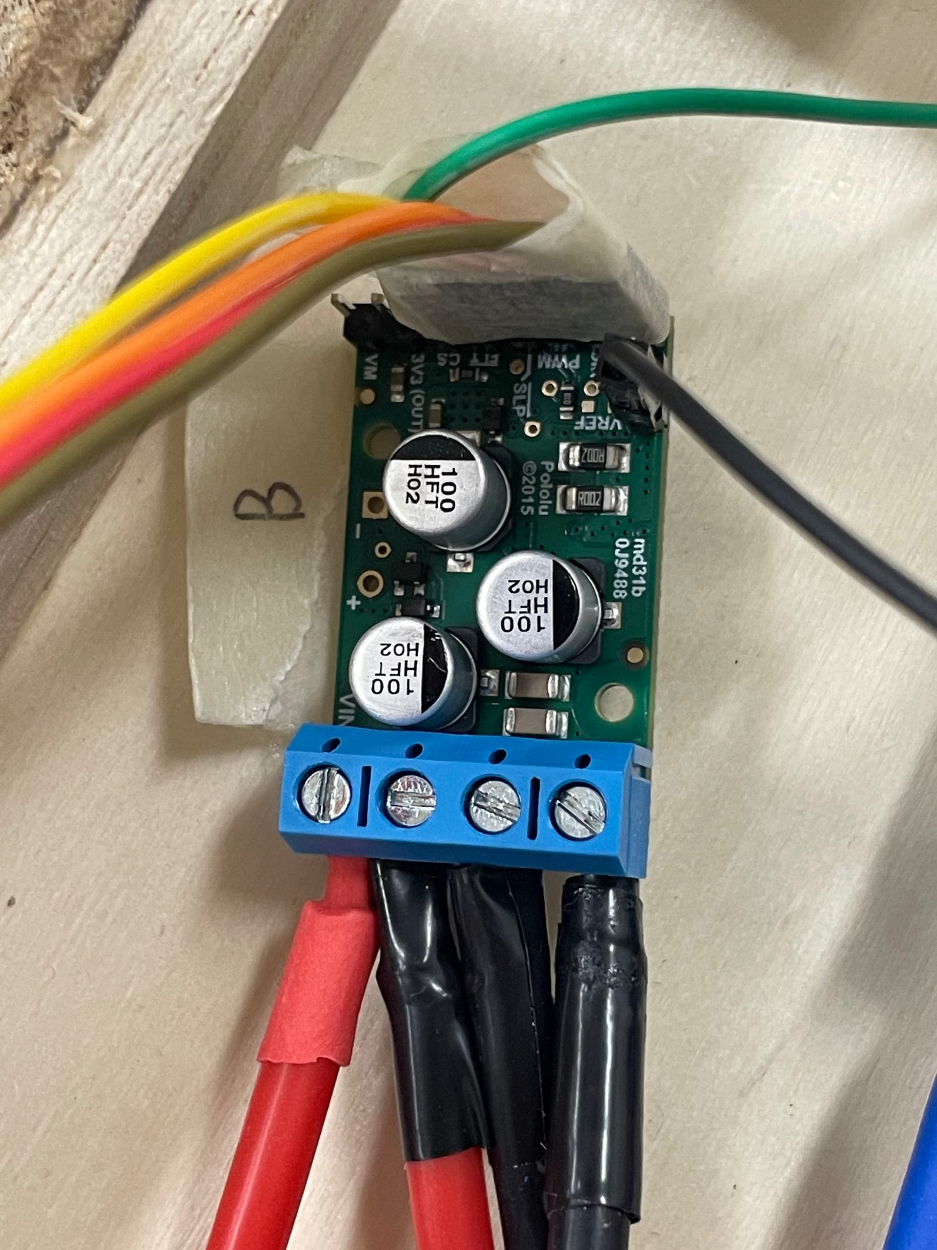
1.2 Where to connect

  • and - terminals, power input terminals VIN and GND, or motor output terminals outA and outB.
    I’m worried about which one of these three should be drawn and connected. When I looked it up, it was supposed to be pulled out from the VIN and GND terminals, is that correct? Or should I connect it to the + and - terminals that were written as capacitors only?
  1. overcurrent
    Wheelchair motors are said to have more than double peak current on first run. To limit the rated current, I’ve put a 20A fuse on the power line that goes into the motor drive, but I can’t limit the peak…

2.1 Added current limiting resistor
How about limiting it to about 30A to prevent overcurrent?
It says in the ‘Current Detection and Limitation’ section, ‘Adding 100kΩ resistance lowers the current limit to approximately 29A’. Should I add 100kΩ between vref and gnd?

2.2 When blocking
If you limit it to this, I’m curious about the situation when it’s blocked beyond 30A.
For example, if the pwm value over 30A is A, limit it when it’s above A and if it’s below A, is it working normally, or block it when it’s above A and it can’t work until it stabilizes.

2.3 How to reset after blocking
If it is blocked, I would like to know how to reset it again (for example, reset the sleep pin or vref pin by giving it a low-high value).
I tried connecting between vref and gnd last time because there is 3.9kΩ resistance. Actually, I should have bought 3.9Ω on the calculation, but I bought the wrong product. If you add 3.9kΩ, in theory, no current is flowing at all. That’s why the motor drive suddenly stopped working. Since then, I’ve removed the motor drive from the wheelchair and repeatedly changed the settings several times.
Initialize by giving low-high to the sleep pin, software dragging and releasing the VREF pin to 0V for 0.5 to 1 second, physically attaching and releasing the vref pin with the gnd for a while, connecting a resistor to the motor drive power input line to remove residual power, etc… I don’t know which part helped with the resolution, but after a day, it worked fine. (The fault value was normal in the first place, so it didn’t seem like the internal circuit was broken.)
Anyway, so please let me know if you have a professional way to reset it.

  1. Lastly, if you think there is a cause of the breakdown, I would appreciate it if you could let me know. Thank you for reading the long article.

Hello.

We have a few different products with 24v21 in the name, but it sounds like you are talking about the Pololu G2 High-Power Motor Driver 24v21.

I am sorry to hear you are having trouble with your drivers. You proposed several different ideas, but it is hard to know with certainty whether those ideas will help without knowing more about the system and what is going on with it. Can you provide more details (datasheets or product page links would be ideal) about your motors and power supply and post some pictures of your system that show all of your connections, including close ups of the top and bottom sides of some of your boards?

Also, please provide more specific information about what the system was doing when the previous drivers stopped working, For example, were they all working for a while before they failed, or did they fail as soon as you tried to use them? Have you tried measuring how much current the motor draws in your setup (such as by using the board’s CS pin), or have you tried monitoring your setup with an oscilloscope? Are there any signs of life from the drivers that stopped working if you try them without a motor attached?

To answer your questions, we strongly recommend connecting an additional capacitor; between the + and - through-holes is an appropriate place to connect it. An inline resistor is usually not necessary. I suggest you monitor the motor voltage during operation to see if the capacitance is adequate by starting with low voltage or low duty cycle tests.

As for your question about the current limiting behavior, you can find information about that in the product page description under the “Current sensing and limiting” header. After the current limiting brakes the motor for around 25µs it will automatically try to apply power again without you needing to conduct any particular reset procedure.

- Patrick

Hello, thank you so much for your kind and quick response.

I think my explanation was a little lacking. First of all, it is correct to talk about Pololu G2 High-Power Motor Driver 24v21 product.

To explain the system a little more, I am using two lithium-ion battery packs 25.2V 12.4Ah connected in parallel. The power cord connects each of the two motor drivers through a 24V switch, a short circuit breaker, and a 20A fuse.
The motor drive has a line connected to each of the two motors on both sides. One motor specification is as follows. (24VDC, 4.0Amax, 4800 RPM, 350W) The power supply lines connected to the board are all using 12AWG of thick lines. Attached is the picture.(The drive in the picture is not broken yet.)

When previous drivers stopped working, they operated (tested) several times before they failed.
Because the equipment I have is limited (I have a multimeter to measure voltage, but I don’t have the equipment to measure current. I also don’t have an oscilloscope), I’ve never measured how much current the motor draws.
Can it be measured using the cs pin on the board? The motor drivers that stopped working see that the fault value is abnormal, so I might have failed trying this and that, but first of all, there is no sign of life.

I’m trying to connect an additional capacitor, how should I check the motor voltage during operation? Should I measure the voltage entering the capacitor?

You mean if you connect 100kΩ of resistance between VREF pin and GND, it will be limited to 29A?


The soldering for the terminal block pins looks suspect on your boards. Can you try remelting those to see if you can clean up the peaks and make sure the joints are fully wetted to the pads? The Adafruit Guide to Excellent Soldering, specifically the “Common Soldering Problems” section might be a useful resource for that.

Sorry, I do not understand what you are saying here. Could you post a schematic or connection diagram? Also, tI think there must be something missing or in error with your motor specifications (24V × 4.0A = 96W, not 350W), so can you post a link to where you got the motors from or a datasheet for them?

Yes, you can measure the motor current with the board’s CS pin. There are some limitations as discussed on the product page under the “Current sensing and limiting” header, but using that pin or using a multimeter to measure current (if you have one that can handle an appropriate amount of current) is probably the easiest way to get some idea of how much power your motor is actually drawing.

I recommend monitoring the supply voltage at VIN, though the + side of your cap or the VM pin would both work and would likely be more convenient points to attach a probe too. This will require oscilloscope (a multimeter will be too slow), so I strongly recommend you get one (or at least, find one that you can access, maybe through a friend or nearby makerspace). You can get a decent one these days for a few hundred dollars and it will save you a lot of time and give you better understanding of your systems, which enables better designs, better margins of operation, etc. Without one, you are left mostly just guessing about what might be happening, which is not a great way to operate.

As explained in the product page description, adding a 100 kΩ resistor between VREF and GND lowers the current limit to approximately 29 A. However, keep in mind that he current limiting threshold is not highly precise.

- Patrick

At the moment, this drive works fine, so it doesn’t seem to be a soldering issue. Of course, the problematic part is visible to me, so I’ll fix it.

I bought a used wheelchair and the wheelchair model was 10 years ago, so the production company didn’t tell me the specifications except for the stickers attached.
My guess is that there appears to be a worm gear connected to the wheelchair motor and the mechanical output is 350w after the gear ratio calculation. That is, the electrical output is expected to be (VI=96W) and the mechanical output is expected to be (τω=350W). I will attach a picture of the sticker attached.

I will seriously consider buying an oscilloscope. But what I can do now is to measure the motor current through the CS pin on the board and set the capacitor specification and current limit resistance by referring to the peak current. Is the current value measured here different from the VIN supply voltage you mentioned earlier?

I suspect to you meant to say electrical input instead of output. Unfortunately that guess does not make sense since the electrical input power cannot be lower than the mechanical output power. It is hard to know for certain, but my suspicion is the “4.0Amax” value is actually for indicating some recommended point for continuous operation instead of stall current (as I first thought given the “max”).

Monitoring the current draw with the CS pin and monitoring the supply voltage with an oscilloscope will tell you about different aspects of your system. Monitoring the motor current the CS pin is a good way to get an idea of the overall load and assess whether it risks overloading the driver. The main purpose of monitoring the supply voltage is to look at what kind of electrical noise and transient voltages the system is generating (such as when the motor is accelerating or decelerating).

- Patrick