baud rate kinda doesn’t matter
the Wixel will use whatever the COM port is opened with
you might want to try the attached
I tried your app and it gives me values …
should be self explanatory - but ask questions if needed
Monitor.zip (283 KB)
baud rate kinda doesn’t matter
the Wixel will use whatever the COM port is opened with
you might want to try the attached
I tried your app and it gives me values …
should be self explanatory - but ask questions if needed
Monitor.zip (283 KB)
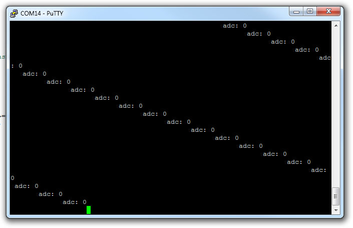
sheepcounter, one problem with the code you last posted is that you never actually set the value of the global variable “avalue” and the name of the parameter to putchar is misleading. Despite these problems, your code did produce output when I opened PuTTY:
I suspect that you either failed to compile the code or failed to load it onto the Wixel, and didn’t realize it. Could you try again? Please note that the Wixel Configuration Utility does not detect changes to wxl files after you open the file. That’s another reason to use the command line. You should delete the wxl file so you can be sure that it gets recreated by the Makefile. You should try running “make clean” again because that really should work: just make sure that you are in wixel-sdk directory when you run the command.
Here is an improved and simplified version of your app. If you successfully compile and load it onto the Wixel, you should see the red LED turn on the green LED indicate the USB status:
#include <wixel.h>
#include <usb.h>
#include <usb_com.h>
#include <adc.h>
#include <stdio.h>

void putchar(char c)
{
    usbComTxSendByte(c);
}

void main()
{
    systemInit();
    usbInit();

    while(1)
    {
        boardService();
        usbComService();

        usbShowStatusWithGreenLed();
        LED_RED(1);

        if (usbComTxAvailable() >= 64)
        {
            printf("adc: %d\r\n",  adcRead(0));
        }
    }
}
–David
Thank you so much for your help!! I used the simplified code and it worked. The only problem was that there was no delay in the printing so the accelerometer values went by way too fast in the terminal window. I added a delay statement using delayMs(1000) and compiled again. The compiling didn’t work and I tried to compile the example blink LED program (using the command prompt) and it didn’t work. Then I downloaded the example LED program using the configuration utility, and it downloaded. I tried to download the robot_project again and it didn’t work. I removed the app file, did “clean”, build all, used the command prompt, and now it doesn’t download! You mentioned that you are trying to create a new “make”…does this scenario seem like a common problem with the current make? Also why do you need to clean all and build all instead of doing this for a single app?
Adding a blocking delay such as delayMs(1000) is a bad idea because usbComService() needs to be called at least every 50 ms to attend to the USB connection. The USB spec says that some control transfers need to be answered within 50 ms and the CC2511 hardware can not do this automatically. Also there are other functions you probably want to call more often than once per second: boardService, usbShowStatusWithGreenLed.
One workaround would be to write your own delay function that calls usbComService, usbShowStatusWithGreenLed, and boardService while it is delaying. However, I prefer to use the non-blocking approach if possible because it places fewer limitations on your app. See the example_blink_led app for an example of how to regularly schedule a task (toggling the red LED) without blocking other tasks or blocking the execution of the main loop.
–David
It sounds like a lot of things in the build process aren’t working for you. What error messages or unexpected behavior are you getting? Is it always the same error message from before?
make: Interrupt/Exception caught (code = 0xc0000005, addr = 0x0x416638)
This means that there is some internal bug in make that is causing it to crash. What you are experiencing is not common (yet). I’ve only heard of this error happening for you and mmcp42, but for mmcp42 the error only happened sometimes.
As a workaround, you could make a batch file that compiles everything you need to compile and forget about using make, but that is not a great solution. What would be better is if you work with be to debug make. I don’t know how to reproduce the problem on any of my computers, so I would send you a debug version of make and tell you how to run gdb to see where the crash is occurring. Do you want to do that? I have already fixed one bug in GNU Make that was affecting Wixel users and it seems like you’ve found another.
You wouldn’t need to clean all and build all if make was working correctly.
–David
Thanks, that would be really helpful to use a debug version of make because it’s been unpredictable. I get the “Interrupt/Exception caught” error sometimes. As I said in my previous post, I couldn’t get the app file to update after doing clean and build. I didn’t see an error message. Doing the “make” in the command prompt didn’t work and I resorted to using the Wixel configuration utility to download the example LED program.
Sorry, maybe my last post wasn’t very clear. There’s a big difference between a “debug version of Make” and a fixed version of Make. I don’t have a fixed version of Make to give you because I have not yet identified the bug and fixed it. Do you want to help me identify the bug by installing some development tools on your computer and following some instructions so I can see why make is crashing? Note that even after we do this, there is no guarantee that I’ll be able to fix the bug but it will be a step in the right direction.
You say that you didn’t see an error message. Did make produce any output at all? The best way to see if make produced any output is to run it at the Command Prompt; you won’t see the output from make in Eclipse unless you have the right view open (the Console).
–David
I would be happy to install development tools to find out why make is crashing. The example blink LED program is currently on the Wixel and I tried to download the accelerometer program using the command prompt but the blink LED program is still running. Make did produce output in the command prompt and I have the end of the output attached.
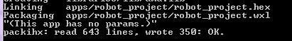
From that screenshot it looks like make could be working. Are you sure you invoked make with the correct command to actually load the program on to a Wixel, which is “make load_robot_project”?
Ok, here’s what you can do to help me identify the bug in Make:
If anything goes wrong during this process, please provide as many details as you can about what exactly you did and what went wrong.
–David
gnumake_debug_1.zip (1.49 MB)
Wow I actually did forget the “load_” part of “make load_robot_project” so that is why it wasn’t downloading.
I had only got the “Interrupt/Exception caught…” error in the console window of eclipse after doing “build all”, and never saw this error in the command prompt. For some reason I am not getting this error right now. If it happens again I will follow the procedure you gave me. Thank you very much for your help!
Ok, I’m glad things are working better for you now! --David
Now I’m trying to understand the Wireless Serial App so I can modify it to transmit and receive accelerometer values. I don’t see where RX is defined. I don’t understand how TX is being set up in this code:
// Set up P1_5 to be the radio’s TX debug signal.
P1DIR |= (1<<5);
IOCFG0 = 0b011011;
// P1_5 = PA_PD (TX mode)
Would I connect TX to the analog input pin that I want to obtain data from to transmit? Does RX need to be connected? I’m also confused about the purpose of the control pins because of the note “You do not have to connect anything to the control signal pins in order to send and receive serial data. These pins are optional.”
The “TX debug signal” that you found code for is different from TX. TX and RX are defined in the UART library (uart.lib, uart1.h, uart.c) that the wireless serial app uses.
Connecting the TX pin to an analog input pin does not make sense. The TX pin is for transmitting TTL serial bytes (for example to another microcontroller’s RX line). The analog input pins on the Wixel are for measuring voltage levels between 0 and 3.3V (for example from your accelerometer outputs).
You would connect the Wixel’s RX line if you want to receive TTL serial bytes from something (for example another microcontroller’s TX line). I’m not sure if you need to connect the RX line in your application because I’m a little unclear on what exactly you are trying to do. If you just want to transmit the accelerometer values wirelessly and display them on your computer then you don’t need to connect any RX lines.
The control pins can be used for many things. On our Wixel Shield for Arduino, we use a control line to reset the AVR microcontroller, enabling wireless Arduino programming.
–David
I want to transmit and receive accelerometer values back and forth between two Wixels. When the first Wixel transmits, the second one receives, and then the second one transmits and the first Wixel receives. Before I try to do this, I think I should write a simple program to transmit values from one Wixel to another Wixel that is connected to the computer so I can see the received value. I’m still confused about what to connect and how to modify the program.
Connections
You have two Wixels, so lets name them Wixel A and Wixel B. You should connect Wixel A to your accelerometer so it can read the value of the accelerometer. You already figured out how to connect a Wixel to an accelerometer, but if you have forgotten then let me know and I can help you do it again. Wixel A and the accelerometer will need to be powered by something. You can power them either from USB or from a 2.7-6.5 V battery connected to the Wixel’s GND/VIN pins, it’s up to you. If you are unsure about how to connect power, let me know.
Wixel B should be connected to the computer via USB so it can report the accelerometer values it receives to the computer via USB. No other connections are necessary for Wixel B.
Software
Wixel B can run an unmodified version of the wireless serial app, with its default settings. It will detect that it is only being powered by USB, so it will go in to USB-to-Radio mode, which is exactly what you want.
Wixel A should run a modified version of the wireless serial app. You would need to add some code to the main loop of the app that periodically reads the accelerometer values and attempts to send them to the other Wixel. You can look in the example_blink_led app to see an example of how to perform a task periodically (instead of constantly) in a non-blocking way. The code I posted earlier shows you how to read an accelerometer value and send it to the USB virtual COM port using the usbComTx functions. All you need to do is change that code to use radioComTx functions, which are documented here:
pololu.github.com/wixel-sdk/radio__com_8h.html
The usbComTx function are very similar to the radioComTx functions, so it should be easy to change the code. Then insert the relevant bits of that code in to your modified wireless serial app.
–David
Today I wrote a preliminary wireless_adc_tx and wireless_adc_rx app, which you can use to transmit the accelerometer values to your computer and view them in a terminal program. They use the radioQueue library instead of radioCom/radioLink, so there will be lost data but they support having multiple receivers and multiple transmitters.
For now, the documentation is in wireless_adc_rx.c in the latest version of the Wixel SDK.
You can browse or download the latest Wixel SDK on github:
github.com/pololu/wixel-sdk
I call these apps preliminary because we haven’t thought very carefully about them yet and might make major changes in the future. The current version will always be available in the git repository though.
–David
Thank you for your help. As for the code you wrote, is the advantage that I wouldn’t need to connect the receiving Wixel to the computer to see the received value? Just making sure…
I tried to modify the wireless_serial app for the transmitting wixel and got this error:
Here’s the wireless_serial app I modified with an “updateprint” function:
/* wireless_serial app:
 * This app allows you to connect two Wixels together to make a wireless,
 * bidirectional, lossless serial link.
 * See description.txt or the Wixel User's Guide for more information.
 */

/*
 * TODO: To avoid damage, don't enable nDTR and nRTS outputs by default.
 * TODO: use LEDs to give feedback about sending/receiving bytes.
 * TODO: UART flow control.
 * TODO: Obey CDC-ACM Set Line Coding commands:
 *       In USB-RADIO mode, bauds 0-255 would correspond to radio channels.
 * TODO: shut down radio when we are in a different serial mode
 */

/** Dependencies **************************************************************/
#include <wixel.h>

#include <usb.h>
#include <usb_com.h>

#include <radio_com.h>
#include <radio_link.h>

#include <uart1.h>


/** Parameters ****************************************************************/
#define SERIAL_MODE_AUTO        0
#define SERIAL_MODE_USB_RADIO   1
#define SERIAL_MODE_UART_RADIO  2
#define SERIAL_MODE_USB_UART    3

uint32 lastToggle = 0;
int32 CODE param_serial_mode = SERIAL_MODE_AUTO;

int32 CODE param_baud_rate = 9600;

int32 CODE param_nDTR_pin = 10;
int32 CODE param_nRTS_pin = 11;
int32 CODE param_nDSR_pin = 12;
int32 CODE param_nCD_pin = 13;

int32 CODE param_DTR_pin = -1;
int32 CODE param_RTS_pin = -1;
int32 CODE param_DSR_pin = -1;
int32 CODE param_CD_pin = -1;

int32 CODE param_arduino_DTR_pin = 0;

/** Functions *****************************************************************/
void updateLeds()
{
    usbShowStatusWithGreenLed();

    LED_YELLOW(vinPowerPresent());

    // Turn on the red LED if the radio is in the RX_OVERFLOW state.
    // There used to be several bugs in the radio libraries that would cause
    // the radio to go in to this state, but hopefully they are all fixed now.
    if (MARCSTATE == 0x11)
    {
        LED_RED(1);
    }
    else
    {
        LED_RED(0);
    }
}

uint8 ioRxSignals()
{
    uint8 signals = 0;

    if ((param_CD_pin >= 0 && isPinHigh(param_CD_pin)) ||
            (param_nCD_pin >= 0 && !isPinHigh(param_nCD_pin)))
    {
        signals |= 2;
    }

    if ((param_DSR_pin >= 0 && isPinHigh(param_DSR_pin)) ||
            (param_nDSR_pin >= 0 && !isPinHigh(param_nDSR_pin)))
    {
        signals |= 1;
    }

    return signals;
}

void ioTxSignals(uint8 signals)
{
    static uint8 nTrstPulseStartTime;
    static uint8 lastSignals;

    // Inverted outputs
    setDigitalOutput(param_nDTR_pin, (signals & ACM_CONTROL_LINE_DTR) ? 0 : 1);
    setDigitalOutput(param_nRTS_pin, (signals & ACM_CONTROL_LINE_RTS) ? 0 : 1);

    // Non-inverted outputs.
    setDigitalOutput(param_DTR_pin, (signals & ACM_CONTROL_LINE_DTR) ? 1 : 0);
    setDigitalOutput(param_RTS_pin, (signals & ACM_CONTROL_LINE_RTS) ? 1 : 0);

    // Arduino DTR pin.
    if (!(lastSignals & ACM_CONTROL_LINE_DTR) && (signals & ACM_CONTROL_LINE_DTR))
    {
        // We just made a falling edge on the nDTR line, so start a 1-2ms high pulse
        // on the nTRST line.
        setDigitalOutput(param_arduino_DTR_pin, HIGH);
        nTrstPulseStartTime = getMs();
    }
    else if ((uint8)(getMs() - nTrstPulseStartTime) >= 2)
    {
        setDigitalOutput(param_arduino_DTR_pin, LOW);
    }

    lastSignals = signals;
}

uint8 currentSerialMode()
{
    if ((uint8)param_serial_mode > 0 && (uint8)param_serial_mode <= 3)
    {
        return (uint8)param_serial_mode;
    }

    if (usbPowerPresent())
    {
        if (vinPowerPresent())
        {
            return SERIAL_MODE_USB_UART;
        }
        else
        {
            return SERIAL_MODE_USB_RADIO;
        }
    }
    else
    {
        return SERIAL_MODE_UART_RADIO;
    }
}

void usbToRadioService()
{
    uint8 signals;

    // Data
    while(usbComRxAvailable() && radioComTxAvailable())
    {
        radioComTxSendByte(usbComRxReceiveByte());
    }

    while(radioComRxAvailable() && usbComTxAvailable())
    {
        usbComTxSendByte(radioComRxReceiveByte());
    }

    // Control Signals

    radioComTxControlSignals(usbComRxControlSignals() & 3);

    // Need to switch bits 0 and 1 so that DTR pairs up with DSR.
    signals = radioComRxControlSignals();
    usbComTxControlSignals( ((signals & 1) ? 2 : 0) | ((signals & 2) ? 1 : 0));
}

void uartToRadioService()
{
    // Data
    while(uart1RxAvailable() && radioComTxAvailable())
    {
        radioComTxSendByte(uart1RxReceiveByte());
    }

    while(radioComRxAvailable() && uart1TxAvailable())
    {
        uart1TxSendByte(radioComRxReceiveByte());
    }

    // Control Signals.
    ioTxSignals(radioComRxControlSignals());
    radioComTxControlSignals(ioRxSignals());
}

void usbToUartService()
{
    uint8 signals;

    // Data
    while(usbComRxAvailable() && uart1TxAvailable())
    {
        uart1TxSendByte(usbComRxReceiveByte());
    }

    while(uart1RxAvailable() && usbComTxAvailable())
    {
        usbComTxSendByte(uart1RxReceiveByte());
    }

    ioTxSignals(usbComRxControlSignals());

    // Need to switch bits 0 and 1 so that DTR pairs up with DSR.
    signals = ioRxSignals();
    usbComTxControlSignals( ((signals & 1) ? 2 : 0) | ((signals & 2) ? 1 : 0));

    // TODO: report framing, parity, and overrun errors to the USB host here
}


void putchar(char c)
{
	radioComTxSendByte(c);
}

void updateprint()
{

    if (getMs() - lastToggle >= 1000)
    {
    	if (radioComTxAvailable() >= 64)
    	        {

    	            printf("adc: %d\r\n",  adcRead(5));
    	        }
        lastToggle = getMs();
    }
}


void main()
{
    systemInit();

    setDigitalOutput(param_arduino_DTR_pin, LOW);
    ioTxSignals(0);

    usbInit();

    uart1Init();
    uart1SetBaudRate(param_baud_rate);

    if (param_serial_mode != SERIAL_MODE_USB_UART)
    {
        radioComRxEnforceOrdering = 1;
        radioComInit();
    }

    // Set up P1_5 to be the radio's TX debug signal.
    P1DIR |= (1<<5);
    IOCFG0 = 0b011011; // P1_5 = PA_PD (TX mode)

    while(1)
    {
        boardService();
        updateLeds();

        if (param_serial_mode != SERIAL_MODE_USB_UART)
        {
            radioComTxService();
        }

        usbComService();

        switch(currentSerialMode())
        {
        case SERIAL_MODE_USB_RADIO:  usbToRadioService();  break;
        case SERIAL_MODE_UART_RADIO: uartToRadioService(); break;
        case SERIAL_MODE_USB_UART:   usbToUartService();   break;
        }

        updateprint();

    }
}To fix your compilation error, add “#include <stdio.h>” near the top of your code.
The advantage of using the wireless ADC apps is that they already do what you want to do and they are easier to understand than the wireless serial app. You still need to connect a Wixel to a PC and use a terminal program if you want to see the received ADC values (were you hoping for something different?). The documentation is here:
github.com/pololu/wixel-sdk/blob … s_adc_rx.c
–David
Thanks! You wrote “transmit the accelerometer values to your computer” and I thought that meant wirelessly transmitting to the computer (I don’t need that  )
)
I was wondering why it’s necessary to use the radioQueue library if it’s less reliable than the RadioCom library. I only want communication between two Wixels.