
I need help wiring the DRV8825 driver into my existing set up. I have made a typical schematic, showing only one Gecko 201 driver, I actually have three, wired in. The components are, one cnc4pc C-10 bi-directional breakout board, one cnc4pc mini power supply, and three Gecko 201 stepper drives. These have successfully controlled, my K2CNC 12 x 25 desktop c.n.c. gantry router.
I will use the DVR8825, to drive a stepper motor on The Spider, a 3d printer modular extruder head assembly made by Rockcliff.com. I do not know a lot about electronics so I don’t understand advanced terms. Explain things as if I’m 5 yrs. old, very simply. I have been told I need to add a separate power source, a wall wart type, for the DVR8825 board. My mini power supply has seven, 5 v.d.c. connections and, 2 12 v.d.c. I use the 12 v.d.c. for cooling fans and there are three power taps open. Is this suitable or are they correct, in that I need another supply. Find pics and docs.
GECKO DRIVE 201.pdf (474 KB)Photobucket
I hope this is not confusing. I want to know how to wire in the DVR8825 to my system.
From the picture you posted, it looks like the Gecko driver has an interface similar to our DRV8825 stepper motor driver carrier. So you can probably hook it up according to the “Minimal wiring diagram for connecting a microcontroller to a DRV8824/DRV8825 stepper motor driver carrier (full-step mode)” on the DRV8825 carrier’s product page.
You will want to be sure that the output of pins 2 and 3 of your parallel port interface card are 5V. If it is not, you will need to use a voltage divider to lower the voltage to 5V. Also, you should be sure that your 12V power supply can source enough current to run your stepper motors. Otherwise you will need a separate power supply (or supplies) for the DRV8825 carriers and the stepper motors connected to them.
-Derrill
O.K. ,but I need you to be more specific. Can I wire it the same as my Gecko? I have been told that I can. I am also seeking advise from the rockcliff forums, and they have indicated that using the minimal wiring is o.k. also. Please show me some diagrams of your suggested wiring schematic? As I said, like a 5 yr. old. Thank you for your assistance so far, I think I can do this.
I am not sure how much more specific I can be than the “Minimal wiring diagram” already is. In case you are having difficulty finding it on the product page, this is the diagram I am referring to:
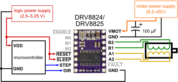
If you have specific questions about what you don’t understand on that diagram, I might be able to answer them.
-Derrill
How do I add the DVR8825 to this typical schematic of my system?
Please explain what are these equal to in my schematic; VDD microcontroller, I recognize GND, Logic Power Supply, Motor Power Supply. Is that a polarized capacitor . How does that figure into my schematic?
Based on the components descriptions I gave here.
download/file.php?mode=view&id=1988
GECKO DRIVE 201.pdf (474 KB)
Short of creating a custom schematic for you (which we cannot do), I do not know how much more help I can give you. If you attempt to make your own schematic with our part in it, I might be able to look at it and offer some additional advice or corrections.
The capacitor is polarized and is to suppress LC voltage spikes that can damage the DRV8825 carrier, it should go across VMOT and GND as shown in the diagram.
-Derrill
GECKO DRIVE 201.pdf (474 KB)If you look at my post you will find a schematic attached with the DVR8825 shown in magenta. It is my typical wiring scheme for my Geko drives. I want to know how to properly add the pololu DVR to that scheme. If you cannot view it there I will add it here.