I would like to connect the MC33926 with the PI and control over Python.
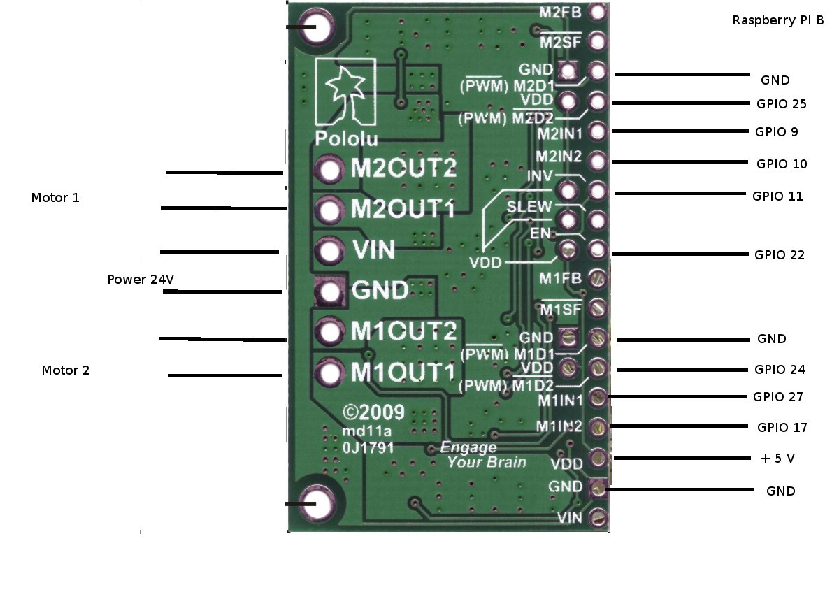
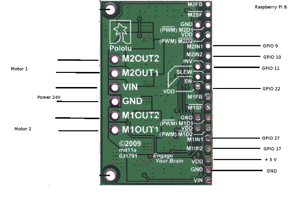
Unfortunately this does not work yet. My current configuration is in the image. to see.
With a motor driver L298N type this code works:
import RPi.GPIO as GPIO
#import distance as abstand
from time import sleep

GPIO.setwarnings(False)
GPIO.setmode(GPIO.BCM)

rr1 = 9
rr2 = 10
lr1 = 27
lr2 = 17
en = 22
inv = 11

GPIO.setup(rr1,GPIO.OUT)
GPIO.setup(rr2,GPIO.OUT)
GPIO.setup(lr1,GPIO.OUT)
GPIO.setup(lr2,GPIO.OUT)
GPIO.setup(en,GPIO.OUT)
GPIO.setup(inv,GPIO.OUT)

GPIO.output(en, True)
GPIO.output(inv, False)
p = GPIO.PWM(27, 50)
p.start(0)

def vor():
	GPIO.output(rr1, True)
	GPIO.output(lr1, True)

def spirale():
	print("Spiralfahrt")
	GPIO.output(rr1, False)
	for i in range(20,100):
		p.ChangeDutyCycle(i)
		sleep(0.6)
	print("Ende")
If the pin’s connected properly, which is still wrong.
Hello.
I am sorry you are having trouble controlling the dual MC33926. Are you doing anything with the disable inputs, D1 and D2? Since they are both active by default, you will have to hold them inactive to enable the motor channels and drive any motors. A few different configurations that you might find helpful for using that driver are mentioned under the “Basic Application Connections” section of that driver’s product page.
-Jon
with this configuration, it works now
import RPi.GPIO as GPIO
#import distance as abstand
from time import sleep

GPIO.setwarnings(False)
GPIO.setmode(GPIO.BCM)

rv   = 10	#rechte Rad vorwärts
rz   = 9	#rechte Rad rückwärts
rpwm = 25	#rechte Rad Geschwindigkeit
lv   = 17	#linke Rad vorwärts
lz   = 27	#linke Rad rückwärts
lpwm = 24	#linke Rad Geschwindigkeit
en   = 22	#Motortreiber aktivieren

GPIO.setup(rv,GPIO.OUT)
GPIO.setup(rz,GPIO.OUT)
GPIO.setup(lv,GPIO.OUT)
GPIO.setup(lz,GPIO.OUT)
GPIO.setup(en,GPIO.OUT)
GPIO.setup(rpwm,GPIO.OUT)
GPIO.setup(lpwm,GPIO.OUT)

GPIO.output(en, True)

pwmr = GPIO.PWM(rpwm, 50)
pwmr.start(0)

pwml = GPIO.PWM(lpwm, 50)
pwml.start(0)

def vor():
	GPIO.output(rv, True)
	GPIO.output(lv, True)
	GPIO.output(rz, False)
	GPIO.output(lz, False)
	pwml.ChangeDutyCycle(100)
	pwmr.ChangeDutyCycle(100)
If I have correctly understood the documentation, it should be possible to give the PWM signal on the N1 and N2 to save even compounds. But how I must then prove D1 and D2?
I am glad you got it working. Like it says in the Pinout table on the driver’s product page, you can apply PWM signals directly to the IN1 and IN2 pins. If you do that, D1 and D2 should be held inactive.
-Jon