Quadrature encoder for the O

For any serious application, a robot must know how far it has traveled and how fast it is going. A wheel or motor encoder is required for such purposes, but of course wheels may still slip. Sadly, few robots on the market offer motors or wheels with encoders.

I previously posted code that makes use of the WheelWatcher by Nubotics, but this unit is very limited in applicability. For those wanting to “roll their own” I offer code to decode a standard quadrature encoder with AB outputs.

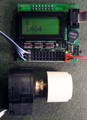
For this application I used a surplus H-P dial encoder (QEDS-7596, 256 stripes or 1024 counts/revolution). The decoding algorithm is from Scott Edwards (see C code for the reference). Despite the algorithm’s simplicity, output changes come thick and fast when you spin the dial and interrupts are required to keep up with the encoder position. I used “interrupt on pin change” to read the AB input on PORTC pins 4&5, which doesn’t seem to miss states even when the dial is rapidly rotated.

For motor control, the interrupt routine should be written in assembler for maximum speed. I would certainly welcome suggestions.

Code with tabs may be downloaded from
uoxray.uoregon.edu/orangutan/encoder.c
Cheers, Jim

/*
Quadrature encoder for the Orangutan, ATmega168

This code assumes that the A and B outputs of a quadrature encoder are connected to PORTC, pins 4&5
If the decoded direction is incorrect, swap the A&B terminals or change the logic of the interrupt
service routine accordingly

The algorithm is from Scott Edwards, in Nuts&Volts Vol 1 Oct. 1995 (Basic Stamp #8, available on line at [rambal.com/descargas/libros/ ... erface.pdf](http://www.rambal.com/descargas/libros/Nuts%20and%20Volts/1/Rotary%20Encoders%20Provide%20Friendly%20Spin%20and%20Grin%20Interface.pdf)

Interrupts are required to avoid missing encoder states. However, if skipped states are not a problem
(e.g a volume control), the decoding can take place in the main routine.
Jim Remington, sjames_remington at yahoo dot com 
*/

#include <stdlib.h>
#include <avr/io.h>
#include <avr/interrupt.h>

//global variables: encoder position and direction of rotation
volatile unsigned int enc_pos;
volatile unsigned char enc_dir;

/*
 PORTC Pin change interrupt service routine. Decodes the encoder.
 For algorithm, see Scott Edwards article from Nuts&Volts V1 Oct. 1995
 (righthand bit of old A,B) xor (lefthand bit of new A,B) => dir.
 Increment or decrement encoder position accordingly
*/

ISR (PCINT1_vect) {
	static unsigned char enc_last=0,enc_now;
	enc_now = (PINC & (3<<4))>>4;  					//read the port pins and shift result to bottom bits
	enc_dir = (enc_last & 1)^((enc_now & 2) >> 1);	//determine direction of rotation
	if(enc_dir==0) enc_pos++; else enc_pos--;		//update encoder position
	enc_last=enc_now;								//remember last state
}

#include "lcd.c"

int main(void)
{
	unsigned char buf[8];

	enc_pos=0;					//Initialize encoder position

	LCDInit();					//Initialize LCD display

	DDRC &=~(3<<4);  			//Port C pins 4 and 5 as input
	PCMSK1 |= (3<<PCINT12);		//enable interrupt on pin change, bits 4&5 PORTC
	PCICR |= 1<<PCIE1;			//enable interrupt on pin change, PORTC
	sei();						//enable global interrupts

	while (1){
		LCDSendCommand(LCD_Line1);		//display current direction of rotation on line 1
		itoa(enc_dir,buf,10);
		LCDPrintString(buf);
		LCDSendCommand(LCD_Line2);		//display current encoder position on line 2
		itoa(enc_pos,buf,10);
		LCDPrintString(buf);
		}
}

Edit: update link to N&V

1 Like

Very cool! Any trouble with the LCD routines getting held up by the interrupts? I imagine any screen problems would be cleared the next time around the main while loop, but it would be nice to be able to see the position count in real time.

-Adam

The delays required for proper LCD function are minimum and can be extended without negative impact. In this example, the interrupts do not seem to cause any problem with the LCD performance. So, the program does display the encoder position in “real time”, that is, as fast as the LCD can be updated.

At the moment, every pin change triggers an interrupt. One could reduce this to just channel A or B, which would halve the decoder resolution. This may be required for my next application in which the rotation of four wheels are to be monitored.

Jim

Note added in proof: I just tested the routine at 512 counts/revolution, which is still a lot, and it works perfectly. This halves the interrupt load on the CPU.

Only one line changes:
PCMSK1 |= (1<<PCINT12); //enable interrupt on pin change, bit 4 PORTC

Man, this is great!

It’s funny, I just finished writing a set of routines for the pin change interrupt stuff. It’s going in the next rev of the library. The example program I did was a low speed rotary encoder, oddly enough.

I used a different algorithm, though. It’s the one that the OOPic uses. One quarter the resolution of Scott Edwards’ routine, but simpler. On a rising edge of A, look at B. If B is a 1, add. If it’s a 0, subtract.

Tom

Yes, that is a simpler algorithm and would work fine with external interrupts INT0 and INT1, because you can discriminate between rising and falling edges in the hardware. I plan to use just this method in my intended application, which has four encoders feeding an ATmega128.

Unfortunately on the Orangutan, INT0 and INT1 are tied up as LCD control lines. With “interrupt on pin change”, there doesn’t seem to be a way to discriminate between rising and falling edges without additional calculations–which the XOR method accomplishes. However, if someone has an idea, great!

Here is the problem: for a motor turning at (say) 5000 rpm, a 512 count encoder interrupts the CPU at 42,700 times per second. If the CPU does nothing else, this leaves just 23 microseconds for the interrupt routine. Divide that by four for four encoders! I’m putting the encoders on the wheels (200 rpm max), but you see the point.

Cheers, Jim

Oh no, I do see your point! Trust me, I do. And because the interrupt code I wrote makes two calls per interrupt (one to the interrupt handler, the second to the user’s routine), it can’t hit that 42k+ interrupt rate, much less do anything else on the side (like process what it detects!)

No, the way I discriminate rising edge versus falling edge is to look at the bit and see if it’s high or low. So that qualifies as an additional calculation. But since I need to look at the other channel’s bit to determine direction, it’s doing an additional calculation already. The bummer is it has to reject half the interrupts and drop back out of the routine if it was called on the wrong edge.

But for 200 RPM max kind of thing it would work just fine, as you said.

I originally wrote the pin change stuff so I could have something that’d call an interrupt when an edge sensor went off. But someone else was looking at making a continuous rotation sensor head with an encoder on it, so that’s how I tested it out. Even 250 interrupts per second isn’t stretching things, and it leaves room to stick encoders on the drive wheels as well.

For something like a servo system with a 5kRPM motor and a 512 count encoder, probably the best bet is to get dedicated quadrature decoder chips so they can keep track of the encoder pulses.

But for a whole slew of applications, a software quadrature decoder is plenty fast enough, and it’s one more piece of hardware that doesn’t have to be integrated into the robot. (Kinda like the toss-up between using an external servo controller versus writing some servo code. If you’ve got the cycles to spare…)

Thanks for posting this, by the way. I hadn’t seen Scott Edwards’ algorithm until now.

Tom

Hi all
i am trying to adjust the quadurature code to use portc pins 6 & 7 as inputs , which i appear to have correct as i can see the pins change in avrstudio etc , but i am blowed if i can get the Interrupt to work as show me the buffer output ,

can someone confirm what the changes need to be , i have try’d using pcint22 all to no avail

i am stuck

PC6 is the reset pin, which you can use as general IO by setting RSTDISBL fuse, but you’d have to be really short on IO pins to want to risk it!

More importantly, there is no PC7! Port C is only a 7 bit IO port (PC0-PC6) on the ATMega168 (assuming you’re using a Mega168 Orangutan like Jim was, or a device using a Mega 8 or 48 family AVR). The AVR Studio simulator will show you an eighth bit of Port C, but only because it’s silly.

So, IF you wanted to change the code to use other pin-change-interrupt pins, first you would need to set those pins as inputs, then you would need to enable interrupts on those pins and on that port (it would help if both pins were in the same port, but its not absolutely necessary), then enable global interrupts, then set up the math in the interrupt service request function (which is just a slick way of condensing four if statements to see which way the encoder has turned).

I would be interested in helping you with that, but we should probably start with your pin choice. Are you indeed using an ATMega168 Orangutan? If not, what device and encoder are you using, and what pins do you have available? Why did you want to use PC6 and PC7?

-Adam

Thanks for the offer of help Adam
this is driving two of us nuts !

i have send you a email with a pdf of the circuit

I can see why this is making you crazy, the board is wired up so that you can use analog feedback (i.e. a potentiometer) or digital feedback (quadrature encoder), but the input header pins are wired together!

So, to get everything straight (in my head too) the board is meant to control two motors, R and L. It has two feedback pins for each motor, RA, RB, LA, and LB. So, if you wanted to use a quadrature encoder for the left motor, you would connect its A and B outputs to the LA and LB pins respectively. The LA, LB, RA, and RB header pins are all connected to pins of PortB on the Atmega, which can be used as pin change interrupts. Super!

Here’s where I think the confusion lies. Pins LA and RA can also be used for analog position feedback from potentiometers (one on each motor), and are also connected to ADC7 and ADC6 respectively. ADC stands for Analog-to-Digital converter, and ADC6 and ADC7 are not part of PortC.

For extra confusion, on the ATMega168 PortC pins 0-5 double as ADC 0-5, but PC6 is the reset pin, and has no ADC function. The ADC6 and ADC7 pins have no other function, but are numbered 6 and 7 to keep with the scheme.

The end of all this is that you want to use PortB as the source of your pin change interrupts! You can probably ignore the connection to the ADC pins.

Another interesting problem is that there is a labeling mistake on the schematic you sent me. It says that PB7 is PCInt6, and PB6 is PCInt7. In reality, Atmel isn’t that cruel, and the numbers should match up, so I’m assuming the pin labeling is correct and the interrupt labeling should be switched. The worst case is that your encoder will count in the opposite direction you expect, which is easily fixed in wiring or software.

SO, Left motor encoder connects to:
LA - PB7 (PCInt7) & ADC7
LB - PB6 (PCInt6)

Right motor encoder connects to:
RA - PB1 (PCInt1) & ADC6
RB - PB2 (PCIint2)

If you’re using two motors with two encoders Jim’s fancy math won’t really do the trick without some modification.

Does this make things a little clearer?

-Adam

Thanks adam for the clarity of your reply , both Marc & myself are very appriciative of the assistance , and i had not seen the error in the pdf either !

i believe Marc is sending you an email too

one of us will get back to you once we have digested your comments more

any solutions welcome too

Dave

Hi adam
Thank you for your help, I have sent you a e-mail and file to the off forum address
If you please I woud like to get your feed back on this program I think I’m close but not close enough.
Thank you for your help and support.
regards
Marc

I’m not sure I’m entirely understanding some of the content of the last few posts and could use some clarification. What I’m trying to accomplish is to have separate quadrature encoders feed back into the motor control cycle - one for each of the motors. My desire would be for the encoders to be driven by interrupts rather than polling. Since the encoders have both an A and a B value I guess this would mean I need 4 interrupt pins ideally on the O (I’m using the OX2 not the original O).

If I understand what you’re saying the 644 only has two available interrupt pins so the only possibly way would be to only use the A lines as interrupts (or B - doesn’t matter which but would only be one per motor) and then would poll the other pin and compare to previous interrupt to determine direction and speed. So the consequence would be that you would lose the quadrature multiplier or at least a component of it - I think you would still get 2x the rated CPR if I understand this right.

Is that right? Or can someone correct me if my thinking is wrong here.

Thanks!

Lee

The 644 actually has three external interrupt pins (PD2, PD3, and PB2), all of which are available for user access on the X2. This still leaves you one interrupt short, unfortunately, but you can get around this by making use of pin-change interrupts (each 644 pin can be configured to produce an interrupt when its value changes using the PCICR, PCMSKx, and PCIFR registers).

You will get better quadrature resolution if you interrupt on every edge of every input, but if your quadrature resolution is high to begin with, interrupting this often might monopolize too much of your MCU. You might be able to get adequate resolution by interrupting on each A transition and noting the value of B when the transition occurs.

- Ben

Hey Ben,

Thanks for the response.

The encoders in my case are on the output shaft downstream of the gearing. The motors max out at 350 rpm or about 6 revs per sec. The encoder is rated at 128 CPR so would give a best case of 512 cpr in full quad mode. So this results in maximum encoder interrupts of less than 3000 tics per second if I calculated right - so even with both motors running don’t you think the 644 should be able to keep up with that - its already significantly less than the 20mhz its being driven by the crystal?

Can you provide a little more detail on how you would use the PCICR, PCMSKx, and PCIFR registers in this scenario?

Thanks!

Lee

The 20MHz mega644 should have no problem keeping up with 3000 interrupts per second.

Pin-change interrupt registers are detailed on page 62 of the mega644’s datasheet. Port A contains pins PCINT0 (PA0) through PCINT7 (PA7), port B contains pins PCINT8 (PB0) through PCINT15 (PB7), port C contains pins PCINT16 (PC0) through PCINT23 (PC7), and port D contains pins PCINT24 (PD0) through PCINT31 (PD7). The PCICR register is used to enable an entire port of pin-change interrupts (setting the PCIE0 bit of PCICR enables pin-change interrupts on port A, for example). The PCMSKx registers let you select which port pins can generate a pin-change interrupt. The following code will enable pin-change interrupts on pins PD3 (PCINT27) and PD7 (PCINT31):

DDRD &= ~(1 << PD3) & ~(1 << PD7); // make PD3 and PD7 inputs
PCMSK3 |= (1 << PCINT27) | (1 << PCINT31); // set pin-change interrupt mask for desired pins
PCICR |= 1 << PCIE3; // enable pin change interrupt for masked pins of port D
sei(); // set global interrupt enable

Now whenever the input on pin PD3 or PD7 changes value, the PCIF3 bit of the PCIFR register will be set and a PCINT3_vect() interrupt will be triggered. This by itself isn’t good enough, however, because you don’t know which pin changed and whether the change was from low to high or from high to low.

The following example shows how you can figure this out (I’ve set it up for pins PA0 - PA3, which you could use as quadrature inputs from your two motors):

unsigned char pinA;  // global for storing state of PINA

void init()
{
    DDRA &= 0xF0;   // make PA0 - PA3 inputs
    PCMSK0 |= 0x0F;    // set pin-change interrupt mask for desired pins
    PCICR |= 1 << PCIE0;    // enable pin change interrupt for masked pins of port A
    pina = PINA;    // save initial state of port A pins
    sei();    // set global interrupt enable
}


void PCINT0_vect()
{
    unsigned char newPinA = PINA;    // get new state of port A pins
    unsigned char changedBits = pinA ^ newPinA;    // if pin has changed, the corresponding changedBits bit will be set
    pinA = newPinA;    // save the new state of the pins

    unsigned char i;
    for (i = 0; i < (1 << 4); i <<= 1)
    {
        if (changedBits & i)
        {
            if (pinA & i)
            {
                // handle pin PAx change from low to high
            }
            else
            {
                // handle pin PAx change from high to low
            }
        }
    }
}

I haven’t tried compiling or testing any of this, but I think it should work.

- Ben

Hi, Folks:

We implemented four channels of PWM with encoders on the 4 independent motor/wheel combinations for our autonomous robot. Since there is some interest in how to do that, I thought I would post the code. We used the Mega128, because it has lots of external interrupts. We also sacrificed encoder resolution for simplicity, so the 500-line encoders are used in 1x mode rather than 4x. This just requires one interrupt and 1 data input line per encoder and the interrupt routine is only 1 line of C.

Main() is only a few lines and takes input from the serial port to set motor direction and PWM. Questions would be gladly answered.

Cheers, Jim

#include <stdio.h>
#include <avr/interrupt.h>
#include <avr/io.h>
#include <avr/eeprom.h>

#define F_CPU 16000000UL	//CPU frequency
#define UART_BAUD  38400

/* macros to set and clear bits in registers */
#define stb(sfr, bit) ((sfr) |= (1 << (bit)))
#define clb(sfr, bit) ((sfr) &= ~(1 << (bit)))

// output compare registers for each motor speed (left uses timer 1, right uses timer 3)
#define PWM0	OCR1A
#define PWM1	OCR3A
#define PWM2	OCR3B
#define PWM3	OCR1B

//GLOBALS

volatile signed int c0,c1,c2,c3;		//encoder click counters for each wheel
volatile unsigned int warp0,warp1,warp2,warp3;  //pwm values


/*	***** 	ENCODER interrupt service routines *****
	- Interrupt (click) occurs on rising edge of INT from encode A-channel
	- Direction is determined from state of B-channel
	- Signed counters c0,c1,c2,c3 count directional clicks per brain polling period
*/
ISR (INT5_vect) {if((PIND & _BV(6))==0) c0++; else c0--;}	// encoder 0.A = PORTE.5 and 0.B = PORTD.6
ISR (INT2_vect) {if((PIND & _BV(1))!=0) c1++; else c1--;}	// 1.A = PORTD.2, 1.B PORTD.1
ISR (INT3_vect) {if((PINB & _BV(7))!=0) c2++; else c2--;}	// 2.A = PORTD.3, 2.B = PORTB.7
ISR (INT6_vect) {if((PINE & _BV(2))==0) c3++; else c3--;}	// 3.A = PORTE.6, 3.B = PORTE.2

// defined functions to set direction (input to H-bridge) and waveform output mode

void fwd0() { stb(PORTD, PD4); stb(TCCR1A, COM1A1); }
void rev0() { clb(PORTD, PD4); stb(TCCR1A, COM1A1); }
void stp0() { clb(PORTD, PD4); clb(TCCR1A, COM1A1); }
void fwd1() { clb(PORTB, PB2); stb(TCCR3A, COM3A1); }
void rev1() { stb(PORTB, PB2); stb(TCCR3A, COM3A1); }
void stp1() { clb(PORTB, PB2); clb(TCCR3A, COM3A1); }
void fwd2() { clb(PORTB, PB3); stb(TCCR3A, COM3B1); }
void rev2() { stb(PORTB, PB3); stb(TCCR3A, COM3B1); }
void stp2() { clb(PORTB, PB3); clb(TCCR3A, COM3B1); }
void fwd3() { stb(PORTD, PD5); stb(TCCR1A, COM1B1); }
void rev3() { clb(PORTD, PD5); stb(TCCR1A, COM1B1); }
void stp3() { clb(PORTD, PD5); clb(TCCR1A, COM1B1); }

void Init()
{
	stb(DDRB, DDB0);	// LED as output

	// direction (forward/reverse) control lines as outputs
	stb(DDRD, DDD4);	// PD4 = motor0
	stb(DDRB, DDB2);	// PB2 = motor1
	stb(DDRB, DDB3);	// PB3 = motor2
	stb(DDRD, DDD5);	// PD5 = motor3

	// PWM control lines as outputs
	stb(DDRB, DDB5);	// PB5 (OC1A) = motor0
	stb(DDRE, DDE3);	// PE3 (OC3A) = motor1
	stb(DDRE, DDE4);	// PE4 (OC3B) = motor2
	stb(DDRB, DDB6);	// PB6 (OC1B) = motor3

	clb(DDRE, DDE7);	// PE7 input for remote enable signal from radio keyfob
	clb(PORTE, PE7);	// disable pull-up resistor on remote enable input

	TCNT1 = 0;	// left side timer counter
	TCNT3 = 0;	// right side timer counter

	// fast PWM mode 5 with 8bit resolution
	TCCR1A = 0x01;	// 00 00 00 01	leftside motors initially disconnected
	TCCR1B = 0x0A;	// 000 01 010	prescaler=8 => 7812.5 Hz
	TCCR3A = 0x01;	// 00 00 00 01	rightside motors initially disconnected
	TCCR3B = 0x0A;	// 000 01 010	prescaler=8 => 7812.5 Hz

	// this bit, WGMnX0, of the waveform generation mode never changes
	clb(TCCR1A, COM1A0);
	clb(TCCR3A, COM3A0);
	clb(TCCR3A, COM3B0);
	clb(TCCR1A, COM1B0);

	// enable external interrupts on rising edge
	stb(EICRB, ISC50); stb(EICRB, ISC51);	// encoder0_A (PORTE.5) rising edge
	stb(EIMSK, INT5);			// encoder0_A INT5 enabled
	stb(EICRA, ISC20); stb(EICRA, ISC21);	// encoder1_A (PORTD.2) rising edge
	stb(EIMSK, INT2);			// encoder1_A INT2 enabled
	stb(EICRA, ISC30); stb(EICRA, ISC31);	// encoder2_A (PORTD.3) rising edge
	stb(EIMSK, INT3);			// encoder2_A INT3 enabled
	stb(EICRB, ISC60); stb(EICRB, ISC61); 	// encoder3_A (PORTE.6) rising edge
	stb(EIMSK, INT6);			// encoder3_A INT6 enabled

	// configure encoder B-ch lines as inputs
	clb(DDRD, DDD6);
	clb(DDRD, DDD1);
	clb(DDRB, DDB7);
	clb(DDRE, DDE2);

	// uart1 setup 38400 8N1
	UBRR0H = 0;
	UBRR0L = (F_CPU / (16UL * UART_BAUD)) - 1;
	stb(UCSR0B, TXEN0);			// tx enable 
	stb(UCSR0B, RXEN0);			// rx enable

	stb(PORTB, PB0);  			// LED on
	c0 = c1 = c2 = c3 = 0;			// initialize encoder counters
	PWM0 = PWM1 = PWM2 = PWM3 = 0;		// redundant since outputs are disconnected anyway

	sei(); 					// enable interrupts (

	}