Dear Jonathan,
Sorry for not replying earlier. Here I have re-soldered the joints and now I am getting some results. Please check if the method that I am using is correct. Please reply as soon as you can. Thanks! Appreciate all your help so far thank you soooo much!
I think the method you are using to calibrate could be improved. First, the QTR array is oriented in a position where the sensors are facing upwards, which exposes them to all of the ambient IR light in your environment. Also, it looks like the piece of paper you are using warps and distorts as you move it across the sensor array, which changes the distance between it and each sensor. I recommend laying the paper flat on your table (with the black tape facing up, of course) and with your hand, moving the sensor array (with sensors facing down, towards the paper) back and forth. The optimal sensing height is 3mm (0.125"), so try to hold sensor level at that height as you calibrate.
Hii Jon , i have recently purchased the QTR 8rc sensor and while running the QTR8rcexamples it shows always 0 in one of the rows is it right reading???one of the rows is always 0 while others show right values.
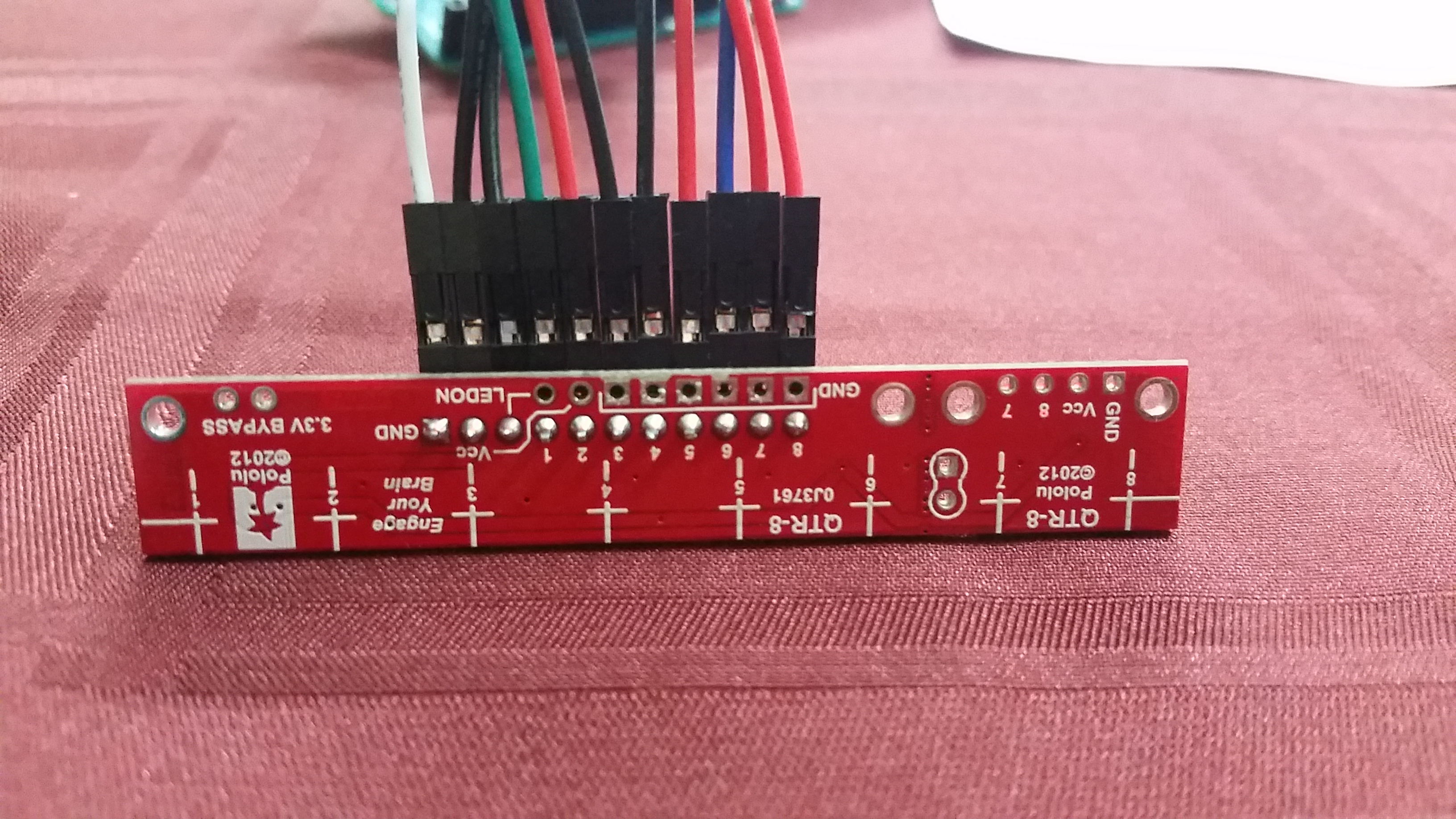
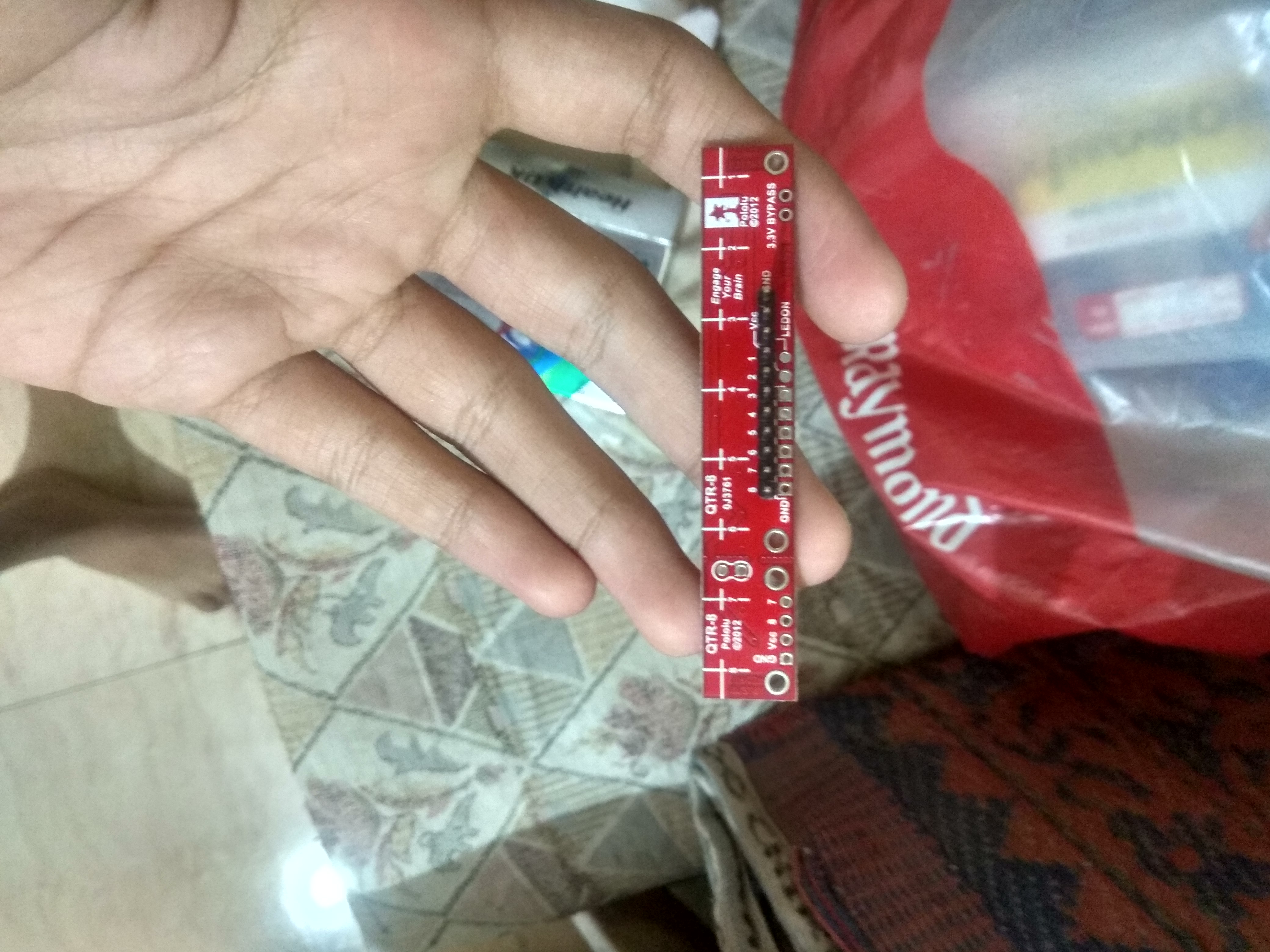
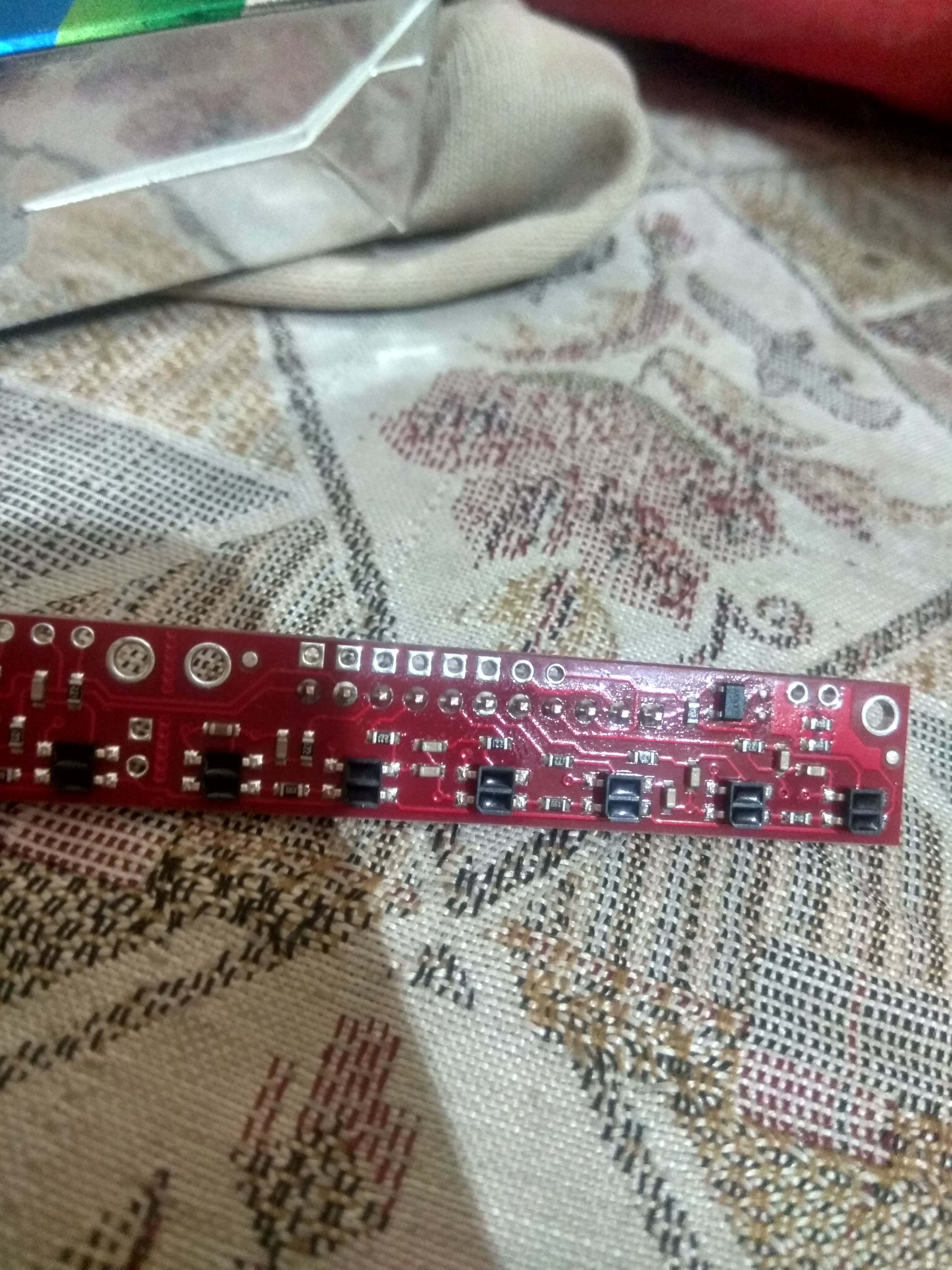
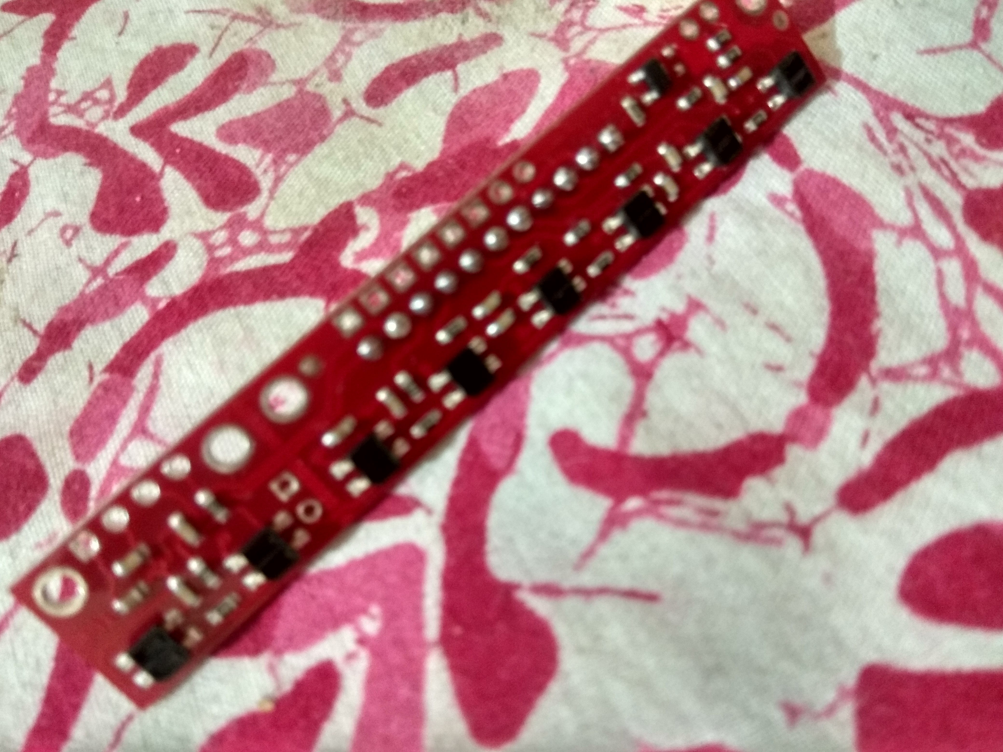
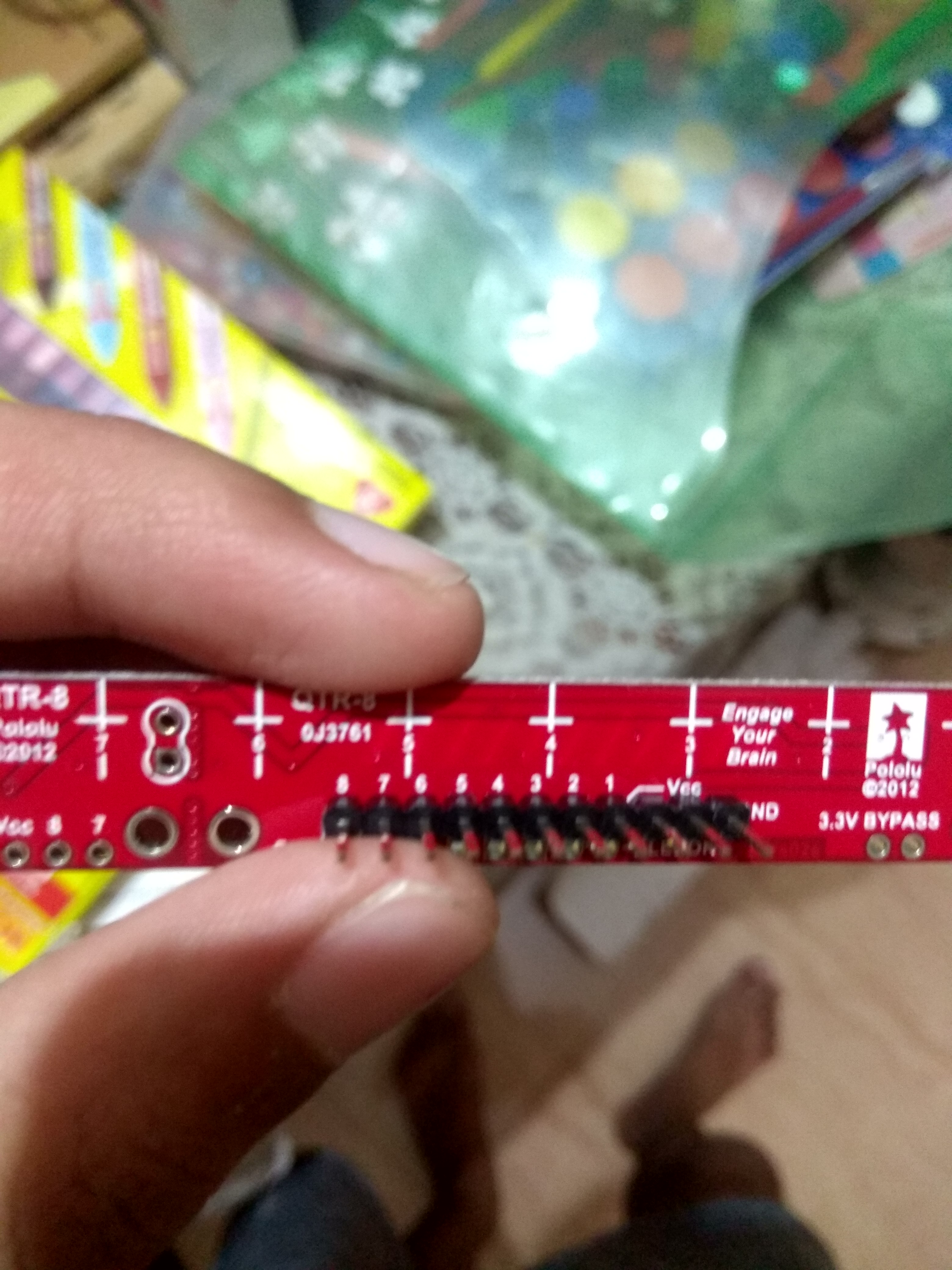
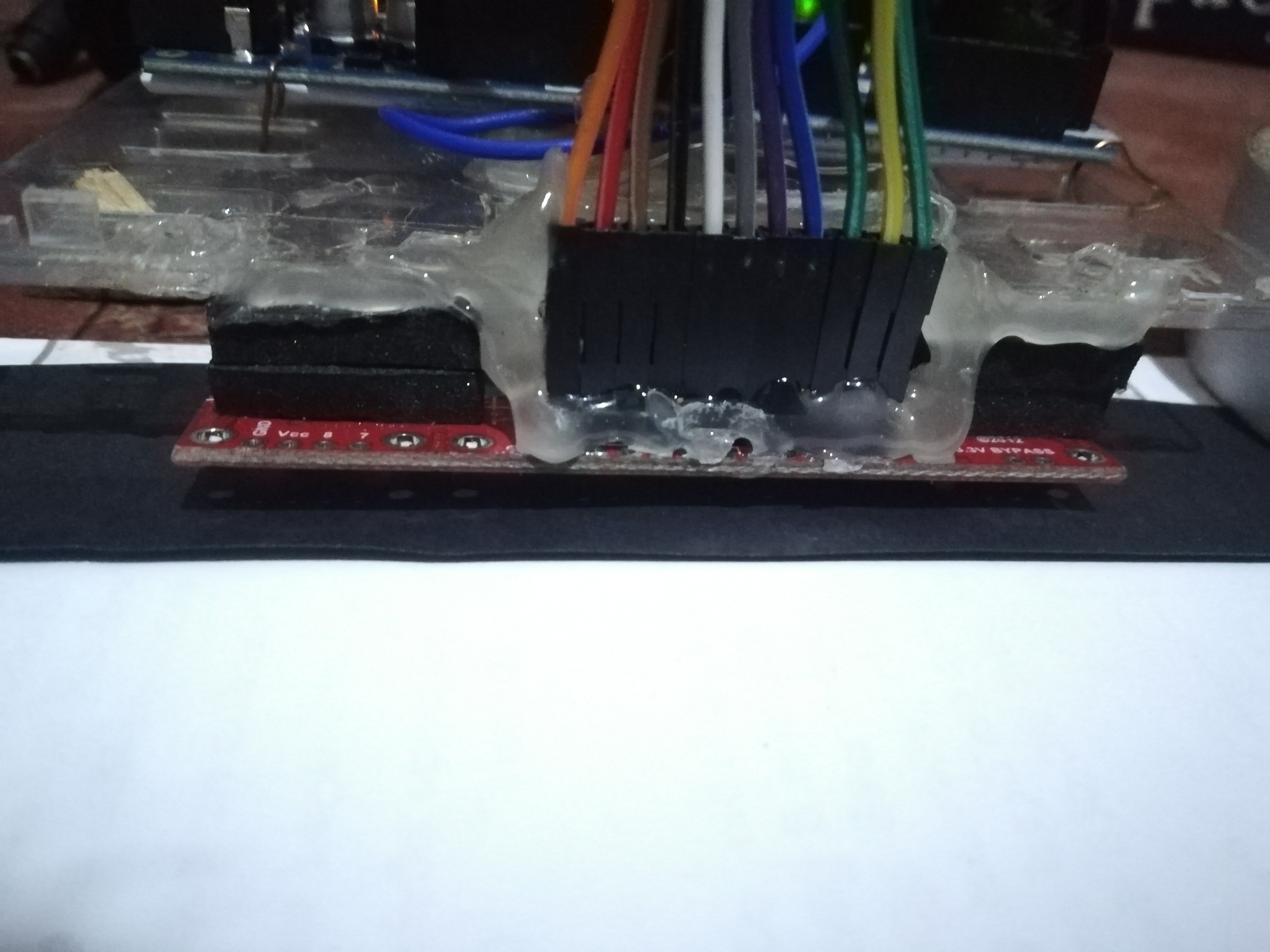
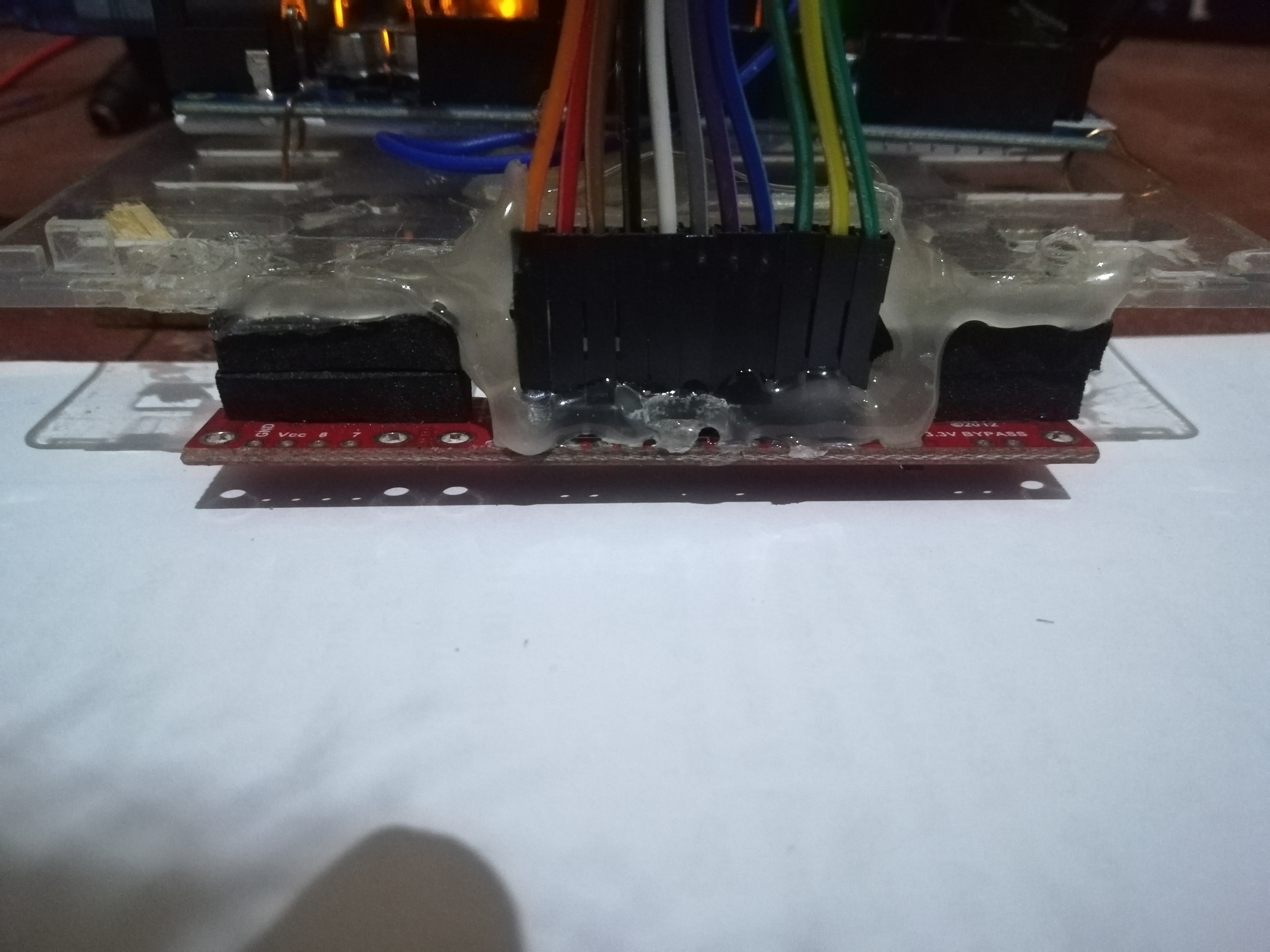
It would help to know more details about the rest of your system. It sounds like you might be using our Arduino libraries; which Arduino are you using? How are you supplying power to your QTR-8RC? Can you post pictures that show your connections and soldered joints? Since the issue you are getting is for a single sensor, it might also help to see pictures of your setup or a video that shows the your system and the behavior you are noticing.
Sorry for inactivity
I am using Arduino uno r3
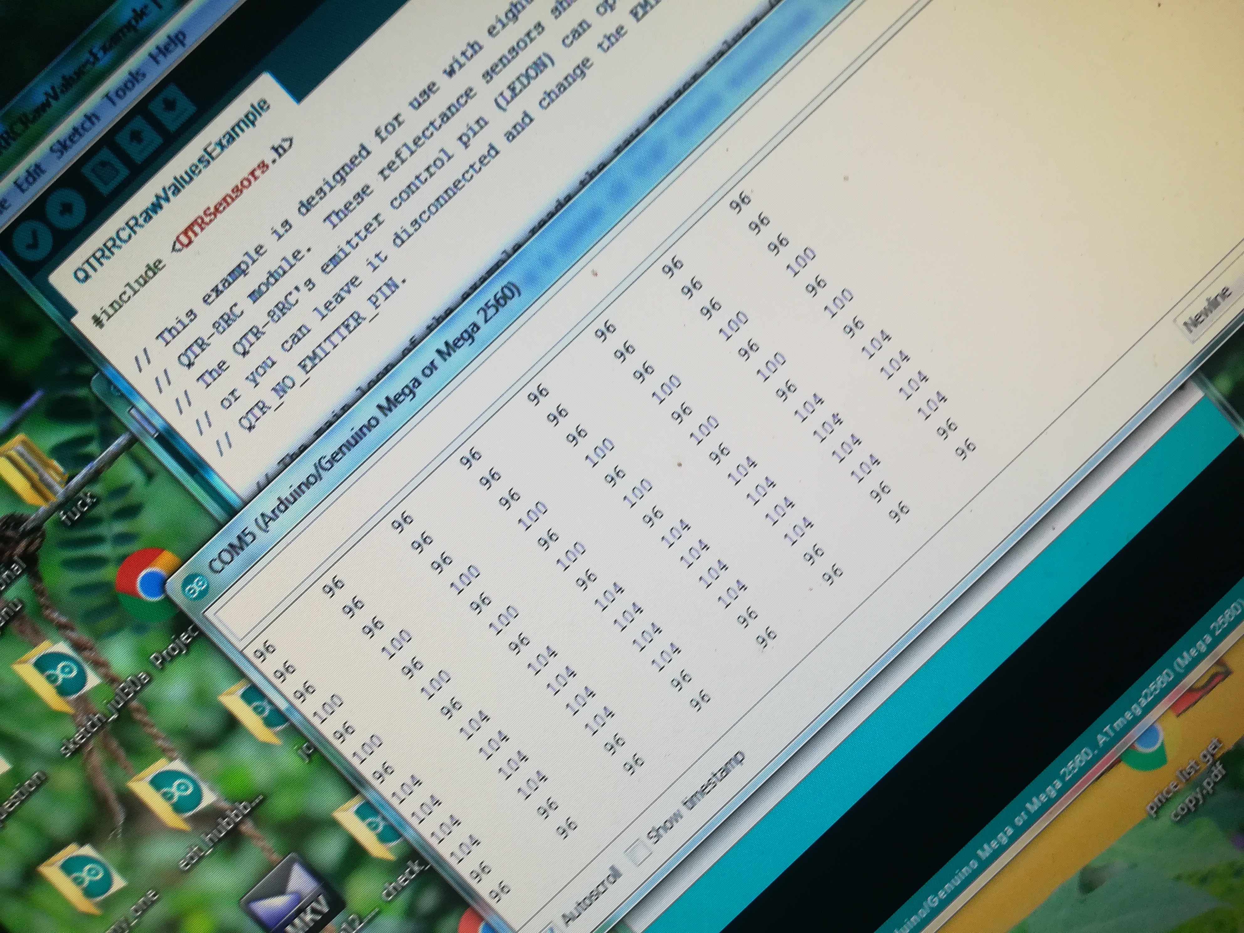
And using your QTR libraries first i tried to run the sensor on QTRRCRAWEXAMPLES.
Then tried using QTRRCEXAMPLES
Here are some pics
Which sensor on the QTR-8RC board is always reading 0? Did you change the pin numbers for the QTRSensorsRC object in the example code to match your physical connections between the QTR sensor array and Arduino Uno? If not, can you change your connections to match the code and see if that fixes the problem? By default, the QTRRCExample and QTRRCRawValuesExample use digital pins 3 through 10 to read sensors 0 through 7, respectively. This is stated in the code comments.
hey i have a prblem in reading values i tried with white paper and black paper but all values are same why i use QTRRCRawValuesExample in qtr libary.i include photos in this post please give me a good solution.thank
Can you post pictures showing the top-side of the QTR-8RC sensor array, particularly the soldering on the board, and the connections between the sensor array and your microcontroller? Also, can you try to use your phone’s camera to verify that each sensor on the board is emitting IR light (for many cameras it should show as purple light)? Do you see any changes to the sensor readings if you point them toward the sun?