1x Qik 2s9v1 Dual Serial Motor Controller
2x 100:1 Micro Metal Gearmotor HP 6V
The Qik manual mentions soldering 0.1uF caps to the motors to suppress noise. Specifically, it recommends one cap between the terminals and one cap between each terminal an the motor can, for three caps total. A quick continuity test on the motors shows that the can is isolated from the terminals. This means the two caps between the terminals and the can are connected in series, and this serial capacitance is connected in parallel with the capacitor sitting between the terminals. So, the total capacitance is:
0.1uF + (1/(1/0.1uF + 1/0.1uF)) = 0.15uF
Is there any reason not to use just one 0.15uF cap between the terminals instead of three 0.1uF caps in the above configuration? Why would the Qik manual recommend a complicated configuration of caps if a simpler alternative would do? Is there anything I don’t understand?
I don’t know the details of the physics, but the quick answer is that it makes a difference, and when you’re talking about noise and electromagnetic interference, almost everything matters. The point in that domain is not that the motor can is isolated from the leads, but that it is itself another component that is part of the overall system that is emitting or suppressing the radiation.
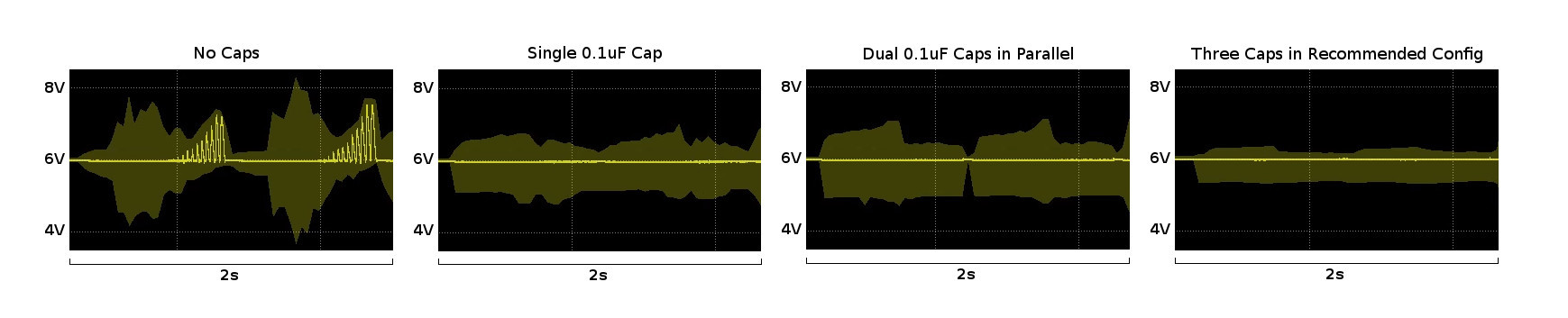
I hooked my scope up to the motor voltage and motor ground on my Qik 2s9v1 and measured the noise there under four configurations of caps. Each time I measured, I powered the Qik up in demo mode. In the attached picture, you can see the voltage measurements for the first two seconds of the demo, enough time for the Qik to move the motor attached to M0 forward and backward once. As you can see, the recommended configuration of caps is most effective at suppressing noise.