Product: Pololu Simple High-Power Motor Controller 18v15 (Fully Assembled)
I’m having trouble getting power from my 7.2V Sub-C Battery Pack to the Pololu Motor Controller.
I have the 6WD Dagu Thumper so I need two of these motor controllers for my robot. I am looking at the PDF that tells me how to wire up the motor controllers. I need to run power and ground into each motor controller.
So I made a cable with the Tamiya connector on one end, and then I’m trying to put a 0.1" 1x1 Housing and pin on the other end.
The problem is that I have to keep making my cable smaller and smaller, and I’m not sure what I’m doing is going to be safe.
The battery pack has a 14AWG cable coming out of it. I attached a 18AWG cable to a Tamiya connector but I need to move to a 22AWG cable in order for the housings to properly fit…
I attached a picture of the cable I’m trying to build… Can someone tell me if what I’m doing is correct or not? I would think there is a simpler way to get power from the battery pack to the motor controller.
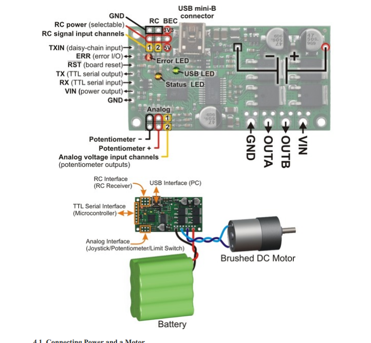
I’m not sure what PDF you are looking at, but it sounds like you are trying to connect power to the smaller Vin and GND connections (the ones with 0.1" male headers). Please note that those connections are only intended as a convenient way to pass the input voltage on to other parts in your system, not as a power input. To connect your battery power, you should connect the bare power leads from your Tamiya connector directly to the screw terminals. More information on connecting power for the SMC can be found in the Connecting Power and a Motor section of its user’s guide.
I’m looking at the Pololu manual. It shows images that I need to connect the battery directly to the motor controller, and then connect the motors to the motor controller.
If I hook the batteries up directly to that white connector on the Thumper then I don’t know how I would hookup the motor controller to power the motors. I was trying to follow the manual at this step.
Thanks.
These images show that the black and red cables from the battery go into the motor controller, and then the blue cables to into the motors.
So are you talking about the screw terminals on the motor controller or on the Thumper?
So if I’m understanding, I need to use two battery packs since I have two motor controllers. I hook the battery into the VIN and Ground on the motor controller, via the blue screw terminals, and then I use the OUT A and OUT B to connect to the screw terminal on the Thumper?
If so, does OUT A go to red and OUT B go to black on the Thumper?
So one motor controller will connect to one side of the Thumper and the other motor controller will connect to the other side.
Lastly, there is so much stuff in this control panel for the motor controllers, I’m really getting lost as to what I should do. Are these motor controllers safe to operate right out of the box? So once I make all the connections, I can use the Thumper, or do I need to have things tweaked just right in the motor controller’s software?
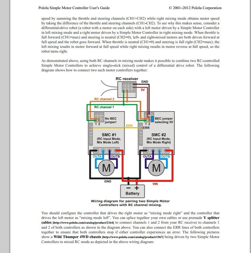
You should only need one battery pack for both motor drivers. To connect it to both controllers you could connect the battery leads to the blue screw terminals on one of the Simple Motor Controllers and then add a jumper to each screw terminal that goes across to the corresponding screw terminal on the second controller. You would use one SMC for each side of the Wild Thumper, connecting the motor leads to the OUTA and OUTB screw terminals on the SMC. Polarity of the motor leads does not matter as you can adjust the direction later with the Simple Motor Control Center. If you want to use RC to control the Simple Motor Controllers, you will need to do some configuration with the control center software. If are using your controllers in RC mode only, you can mostly concentrate on the RC section of the user’s guide and skip over the sections about using the serial interface.
When you say add a jumper between the motor controllers, do you mean just adding an extra piece of wire that goes from the blue screw terminal on one motor controller to the other?
For example, I would hook the red wire of the battery into the VIN connector and then add a second wire that goes from that VIN connector to the VIN connector on the other motor controller?
I think I see where you’re going with it, but this is my first build.
The smaller connectors on the motor controller (the ones I was trying to use before)… Can I use those to power a breadboard, or a 5V fan? I think that’s what you meant by powering other components.
Thanks for all the help.
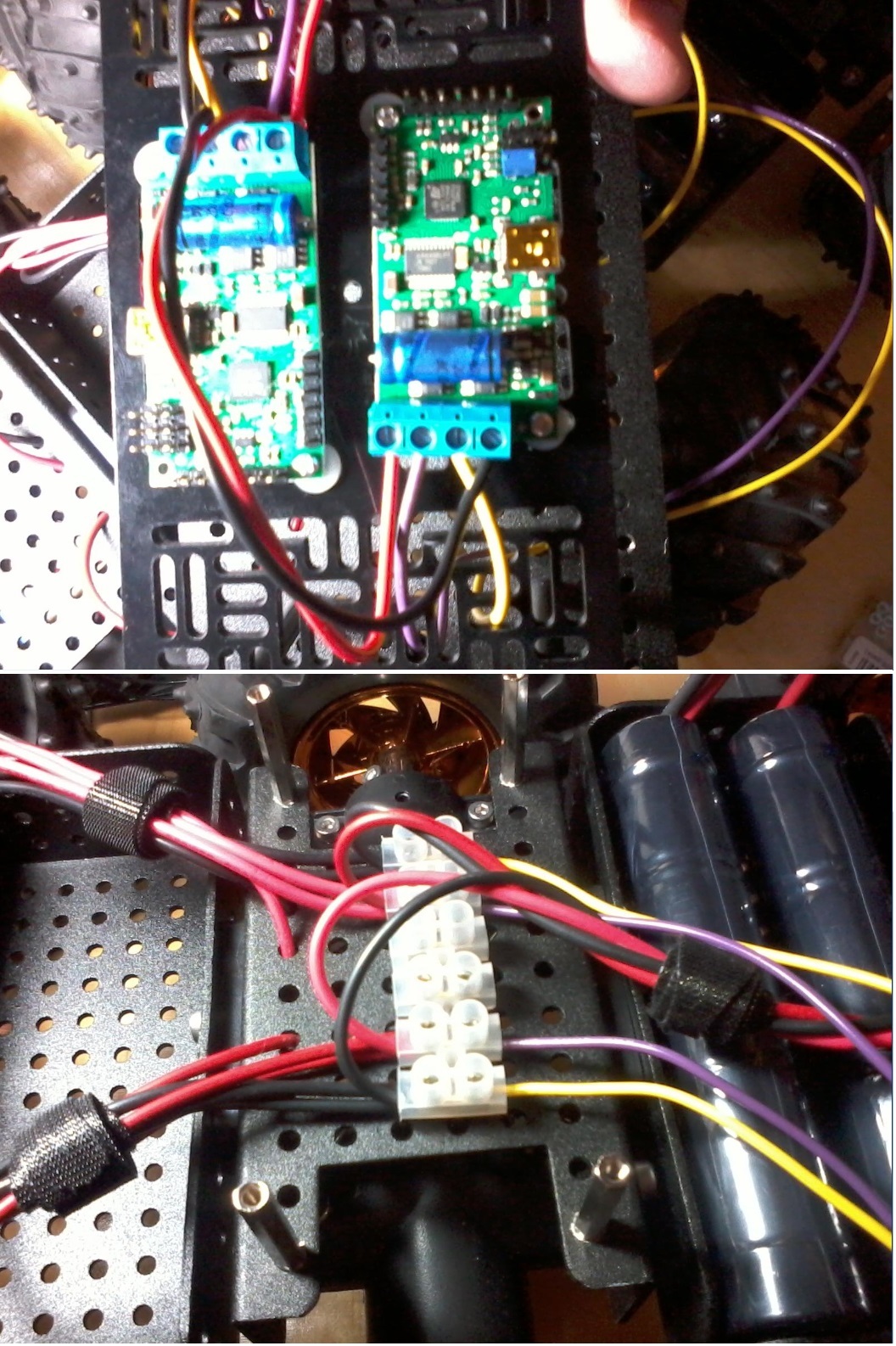
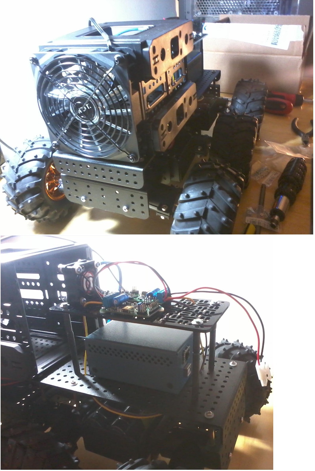
I think I will upload a couple pictures of the “wire up” once I’m done. Maybe you could take a look at what I did, before I turn anything on… I just want to make sure I don’t burn something out.
Yes, the VIN and GND connections sound correct. You can use the smaller VIN and GND connections to power something else. Please note that the voltage will be the same as your battery voltage, so a 5V device might need a regulator to adjust the power level.
I would be glad to take a look at your pictures to verify your setup once you have them posted.
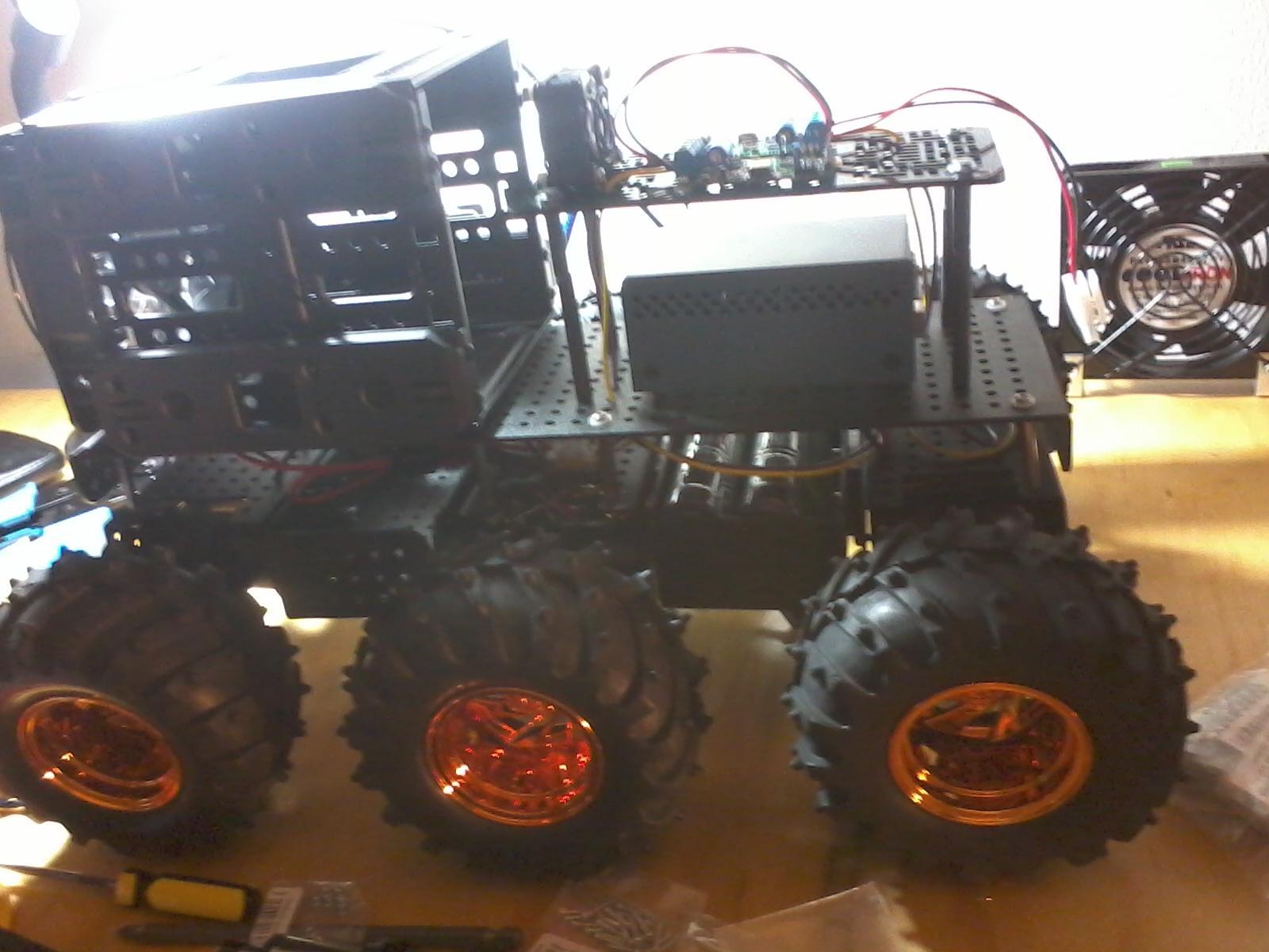
Well sorry, these are really bad pictures, but it’s the best I could do with my phone. Maybe it will help you some. I don’t know.
Anyway…
Black from battery → Ground on motor controller
Red from battery → VIN on motor controller
Ground on both motor controllers are connected via a black wire
VIN on both motor controllers are connected via a red wire
OUT A goes to the red wires screw terminal on the thumper
OUT B goes to the black wires screw terminal on the thumper
And I really hope that 18AWG wire is going to be good enough, because that’s all I could use. Any thicker than that, and I couldn’t place two wires into the VIN/Ground screw terminals on the motor controller because the terminals were too small.
You have a point about the wires. I was not considering the total load of the six motors combined current draw in this setup. If you have two battery packs, you can run one battery pack to each Simple Motor Controller separately and eliminate the jumper connections between them. Alternatively, you could run separate wires from each of the Simple Motor Controllers to one battery. Either of these methods would allow you to use larger gauge wires.