As per the example script, both motors should run forward then back.
Issue:
The motor connected to M1 runs well and as expected, however, the motor connected to M2 runs backwards briefly then changes direction to forward. This is unexpected behaviour and will not work in the buggy we are looking to build.
I have swapped out the motors from M1 to M2 to verify that it is not an issue with the motors.
Can you please provide some advice on how to tackle this? Looks like on the surface the Motor driver unit supplied is faulty but I am open to other explanations.
Thank you for the video and detailed description; that is very strange behavior. We test every unit we make, so your dual driver was probably working at some point. Can you post close up pictures of the both sides of the board that show all of the soldered connections? Can you also look at what is going with an oscilloscope and post some captures of what you find?
Thanks for your response. I am certainly not suggesting that you have shipped an untested product and hopefully it is an easy fix
Unfortunately, I don’t have an oscilloscope. My apologies, this is a very light touch hobby that I have picked up to spend time with my son. Perhaps I will have to get one.
I have, however, tested with a multimeter the voltage that runs to each motor while they are running. Both show 5.5V.
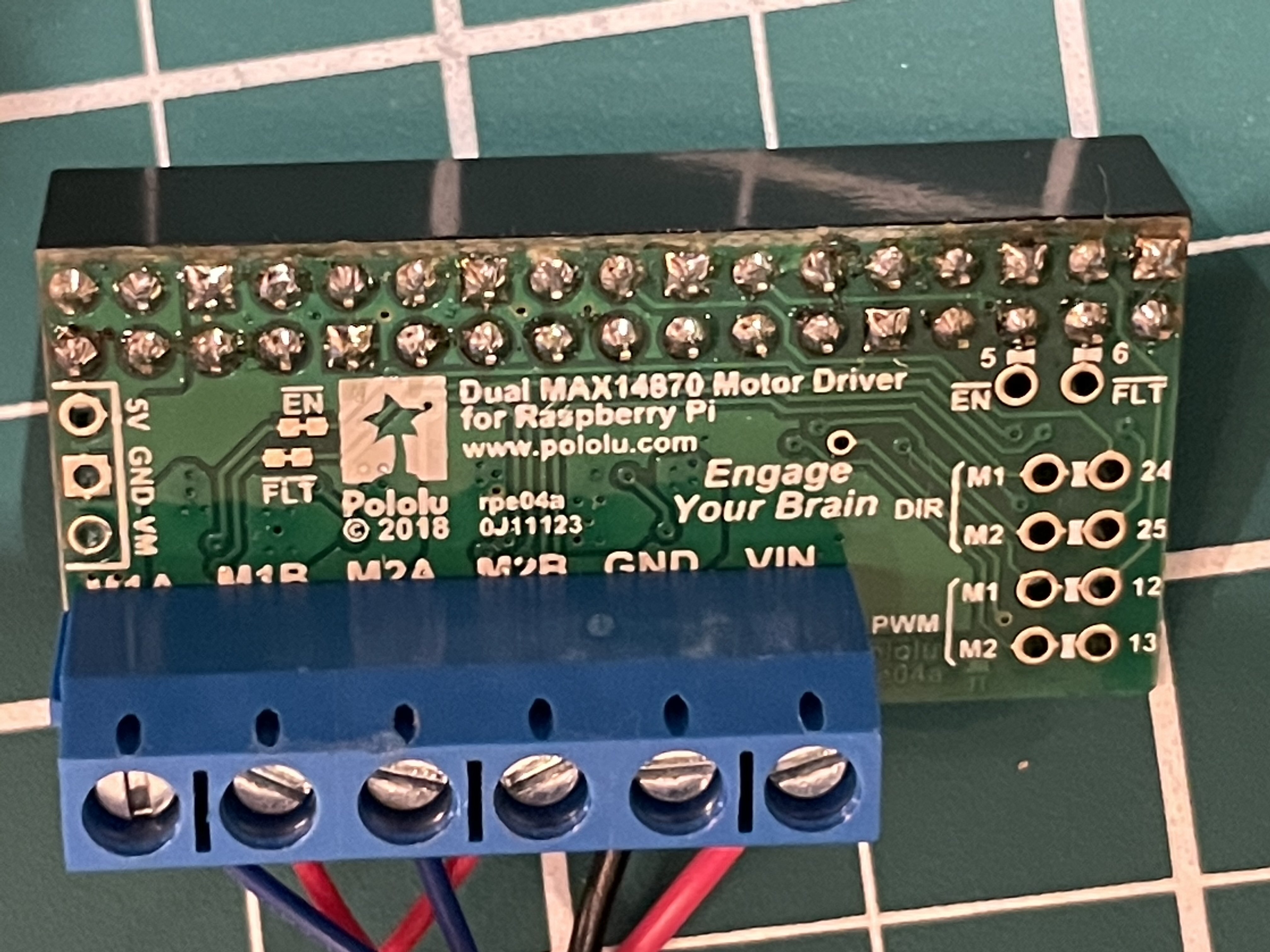
Thanks for the pictures. The soldering and connections look okay. Since you do not have a scope, could you try using your multimeter to monitor what is going on with the driver DIR pins when you run our example program?
By the way, if you think you might start spending more time with this hobby I highly recommend investing in a decent scope, or at least finding one you can access or borrow when needed. You can get one these days for a few hundred dollars, it will save you a lot of time, and it will give you better understanding of your systems, which enables better designs, better margins of operation, etc. Without one, you are left mostly just guessing about what might be happening, which is not a great way to operate.
Thanks Patrick. I’ll look to invest in a scope at some point.
Monitoring the DIR pins, I get a consistent reading of 3.31 volts for both forward and reverse on pins 24 and 25.
In perhaps some good news, it seems that in the process of measuring the voltage of the pins now the motor attached to M2 is will only run in reverse, no longer forward at all.
Just to make sure I understand what is going on, can you confirm the following two points:
When you run the example program you never see the voltage on either of the DIR pins change; they always show about 3.3V.
When you run the example program, M1 turns in both directions, but M2 only goes in one direction.
If that is correct, then I am starting to wonder if your Raspberry Pi’s GPIO pins are working correctly. Is there anything you can do with your Pi to get pins 24 and 25 to change states? What do those pins do if you remove the driver from your Pi, run the example program, and monitor them directly? You might also try testing your driver with another Raspberry Pi if you have one.
Separately, could email your order information to support@pololu.com with a reference to this thread?
For pins 24 and 25, I see 3.3V for the while the program is running reverse commands.
This is correct. Only reverse.
I don’t have an another Pi however, I have run the example program without the hat installed and monitored just GPIO pins 24 and 25. For both of these pins I see the same behaviour. They output 3.3V when the program is running the reverse command.
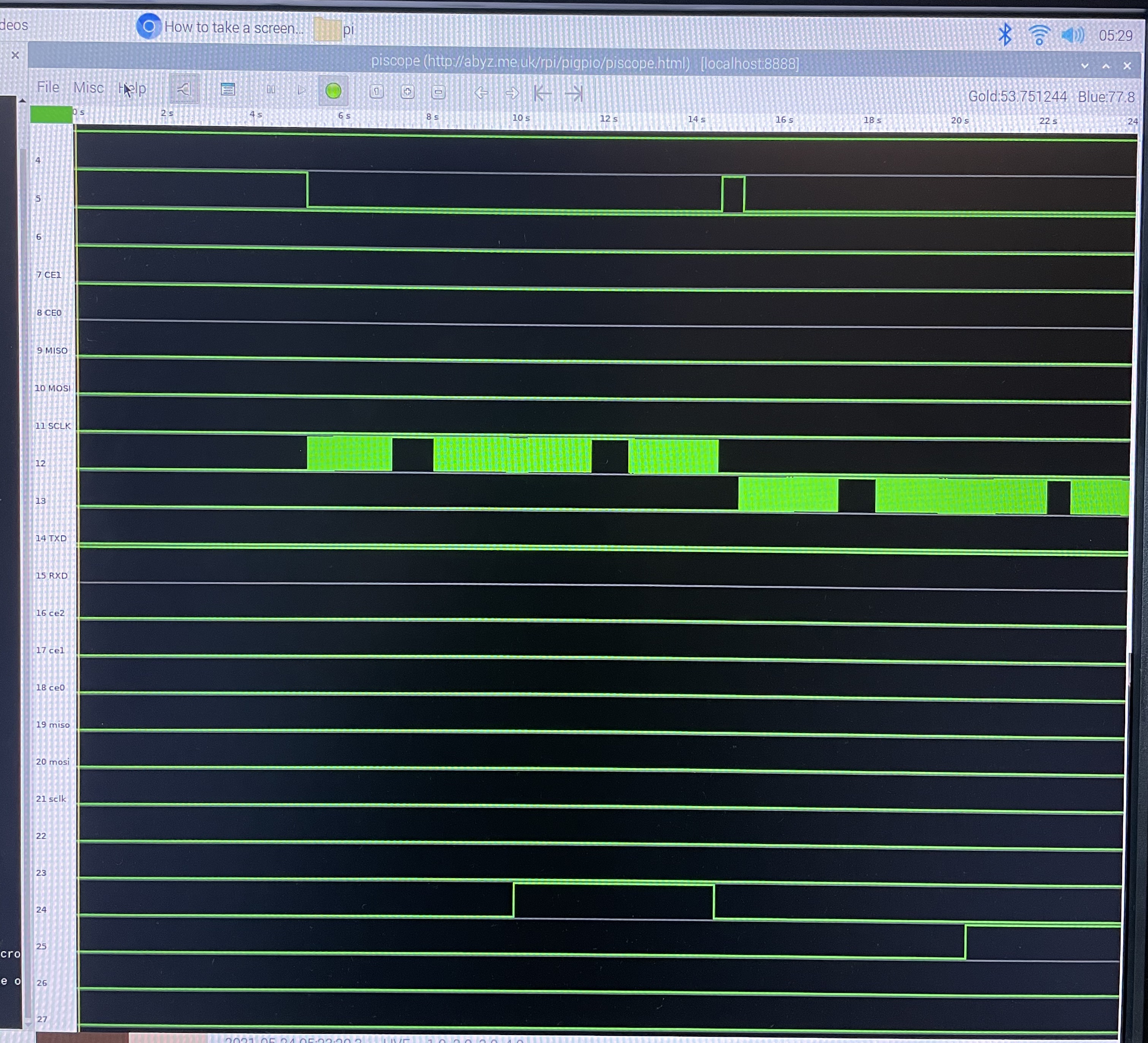
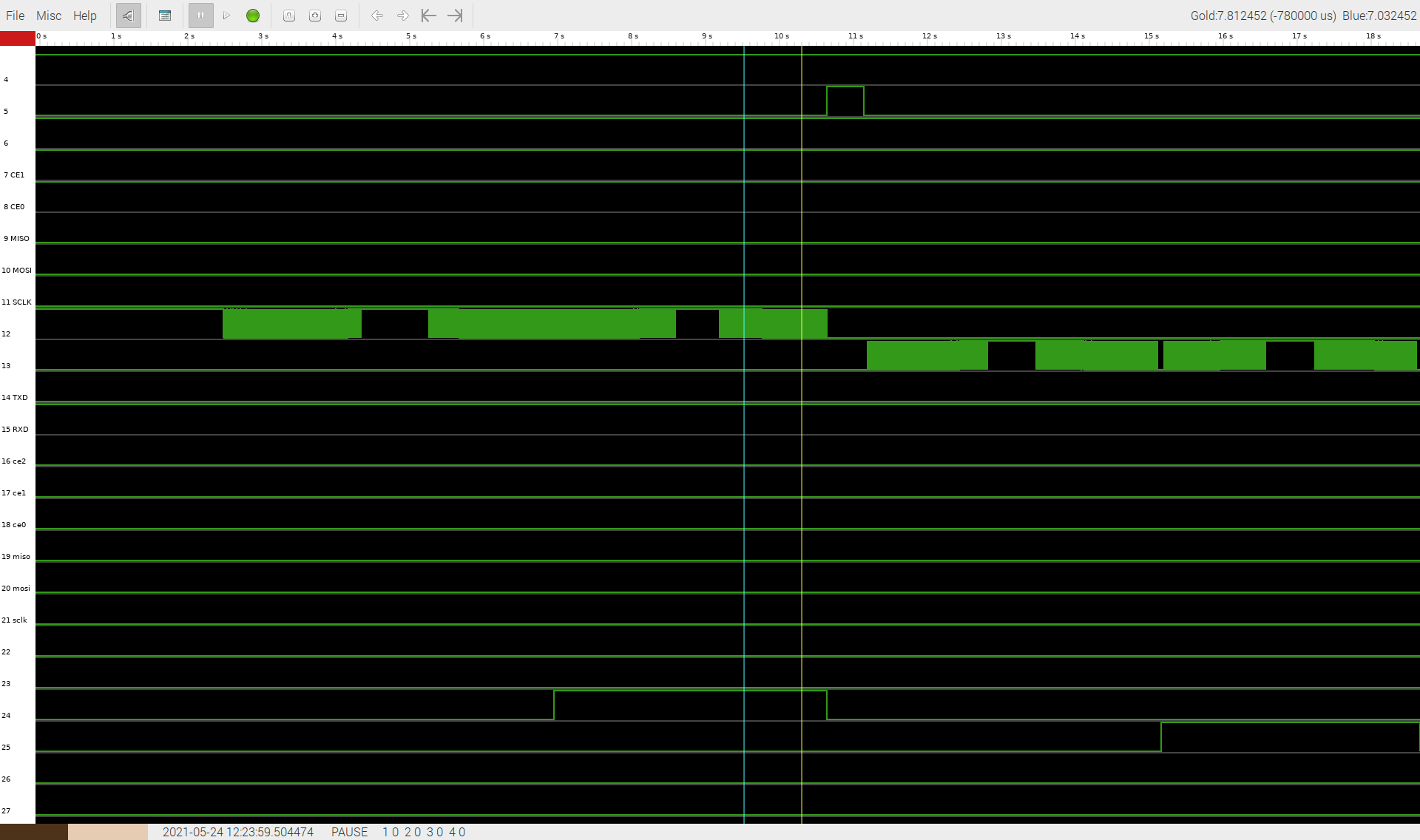
I have also managed to get some readings from an application I found on a Raspberry Pi forum called Piscope. Not sure how useful this is sorry about that poor quality image, I couldn’t get a screenshot out of the Pi.
The below is the reading when I run the example.py script without the driver attached to the Pi.
Using your multimeter (since I am not sure if piscope accurately reflects the state of pins while they are supposed to be outputs) can you see the DIR pins switch to low (0V) when the motors are supposed to be running forward? In other words, are the DIR pins oscillating between 3.3V and 0V? Does it make a difference whether the motor driver is connected?
Also, when M2 is supposed to be running forward, what is it doing instead; is it running backwards or not running at all?