Problems with PIC and VNH2SP30

I am currently trying to control 2 actuators using a VNH2SP30 on each actuator. I am using a PIC16f877a to convert an analog signal into PWM signal and to take inputs of the position of the actuators.

We had all kinds of noise problems with the actuators shutting the PIC off as soon as it entered its slow range, determined by the actuator position. We added a software debounce and that seemed to fix the problem. Before we added the software debounce we tried adding two zener diodes pointing at each other across the motor terminals to squash any back EMF emmited from the motor.

The didodes did not seem to help and once the software debounce was added we had the whole project figured out. I took the system apart and made all my final solder connections. Once this was done we hooked it all back up for a final test. One thing we did not hook back up was the zener diodes. The first actuator worked as before but the second actuator failed. Could the zeners have been helping? Now without the zeners in there could a large enough back EMF spike damaged the controller enough to render it inoperable? When I say inoperable actuator 1 won’t even work now and I tried reflashing the PIC and it still acts the same way.

This project is getting tight on the timeline and hopefully someone has had this problem and can help me out…

Jay

Noise is one thing, but I would be surprised if you were able to permanently damage the motor driver chip operating it as you describe. It has a variety of built-in voltage/short/thermal protection features. I put a VNH3SP30 through some serious abuse with a high-current motor with no external diodes, and the worst it ever did was cause a brief (couple of seconds at most) thermal shutdown.

Now, I’m sure it is possible to destroy one of these chips with a big enough back EMF (has anyone else been able to do that?) but my instinct would be not to focus on the motor driver to the exclusion of looking for the problem elsewhere, either in the power or signal connections or the PIC itself. Can you try to isolate (with an oscilloscope maybe) the breakdown, checking that the PWM signals are actually being output by the PIC, and getting to the motor driver input pins?

Are you using one of the big 40-pin DIP packages and a zif-socket programmer? It’s my own personal bias, but I had lots of problems with those in the past (the PIC16f877 in particular), most likely from my own careless handling of them (not to mention putting them into the programmer backwards on occasion!). I even once had one develop an internal short that destroyed some other chips on a board. If you can’t get your hands on a scope, I would try hooking up the non-functioning motor driver chip to the signal currently going to the functioning one. At least this will let you eliminate some possibilities, and you can check most of your connections with just a multimeter.

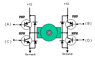
As for the diodes, I’ve never heard of your setup before, but from how you describe it [Terminal–|>z-z<|–Terminal] it sounds like it would still offer some protection from back EMF (at least over the zener’s breakdown voltage) which is better than nothing. If you have managed to destroy your motor driver with back EMF, you might want to switch to a flyback diode setup for more complete protection:

The downside is that this has to be added on the board end, while your setup can just be added across the motor terminals. Anyway, please let us know if you are able to isolate the problem any further, and good luck!

-Adam

Adam,

I am pretty sure the motor controller is fine. I think it is the PIC that is having the troubles. Could that back-emf I am describing harm the PIC to the point of catastrophic failure like I am having?

I have ordered a few more 16f’s from dig-key and hopefully I can get one to program tomorrow and be on my way with the back EMF protection in place.

Also as you were saying witht he PWM output, it goes to crap after this breakdown. I get 0.20 volts at the PWM and the move input to the PIC will not trigger anything to happen.

I know its the PIC I just don’t want it to happen again. That is were I am trying to get with some help from the forum.

Jay

Sorry, when you said “the controller” I wasn’t sure if you were referring to the motor controller or the microcontroller. If the only connection between the pic and the motor controller was the PWM signal (and possibly the “enable” pin, and of course the common ground) then no, I wouldn’t expect back EMF from the motor to have damaged the PIC, especially without damaging the motor driver chip itself. This doesn’t mean it isn’t possible, but I would be surprised.

If you’re concerned about back EMF (i.e. if your motor is HUGE) you should put your zener diodes back in, just to be sure. Another good precaution, if you haven’t already, would be to add small resistors (on the order of 1-5 Kohm) to all the digital lines connecting the motor driver chip and your PIC. This would add some protection from very brief voltage spikes, like the kind you get when you suddenly cut power to a DC motor.

I still don’t have much faith in those big PICs though. When my old lab was using PIC16f877’s they had a lifespan of maybe 30-40 round-trips from the programmer to the robot until they would die in some inexplicable way. Maybe we just all generated a lot of static electricity. Anyway, good idea ordering more than one!

-Adam

Thanks Adam,

We have the resistors inline on the digital pins. In our application we only have really one power source for the project. The motor controller and the PIC share that source which is why I am wondering if the back EMF could be the culprit.

Hopefully tomorrow we can get a PIC to flash and be on our way to making this project work.

Jay

Huh, I didn’t think about that avenue of destruction. Are the motor and PIC being fed directly from the same (5V?) power source, or does the PIC have a dedicated voltage regulator?

I’m always wary about connecting microcontrollers directly to power supplies, especially if other things are sharing that power. In the absence of a dedicated regulator you would want something to further protect the pic, like a 5V zener diode in reverse bias across the PIC power and ground pins, or a nice big capacitor to absorb short spikes, or both.

-Adam

We have seperate Vregs for the motor controller and the PIC. The zener is something we have not tried however, or the large capacitor. I ill pick both those up tonight and implament them in the morning when my new PICs arive. Hopefully this does the trick…

J~

Oh good. Unless its a total piece of junk, a separate voltage regulator should be plenty of protection for the PIC. If you want to add capacitors for extra-smoothness, you might want something like a 100uF cap on the supply side of the regulator, and a 10uF cap on the output side.

-Adam

Like I said I will add back in the back EMF protection we made and then possibly add the cap on the input to the Vreg. We have a cap directly off the Vreg as well as one at each power and ground input into the Pic.

Crossing my fingers b/c if tomorrow falls apart then I am SOL on my deadline…

Jay

Small question…

Adam, do you use PICs with your line of work? If you are using a high current motor like I am with such a problem what would you do? Also, is there a better model to be using for my purpose?

Just a few questions for you when you get a moment.

Thanks,

Jay

That’s a fun question, I never really thought of myself as having a “Line of work”. I have worked for two University robotics labs (previously the Biorobotics lab at Carnegie Mellon University, currently the Mobile Robotics Lab at the University of Michigan), and we inevitably end up using a variety of microcontrollers.

At CMU I was working mostly with PICs, just because I came in on a project that was already using them, so we had a stock and some equipment and software, but I never got really comfortable with them. Other projects in the lab used other microcontrollers, it was basically the personal preference of whoever started up a new project.

My current lab has used mainly Motorola microcontrollers in the past, and while they are certainly more powerful, they are a lot harder to get into using, and there isn’t so much of a support community for them. On more than one occasion when we needed something done quickly, instead of trying to use an existing Motorola setup, someone would run home and grab a Basic Stamp, or a PIC, or a BOE, or a Handy Cricket, or an OOPIC, or in my case, an AVR.

Recently, we’ve been using ATMegas coupled with ATTinys more than anything else. Part of this is because I have been here longer and more of the old-timers have moved on, so its more my choice, but I’m not the only one. I think a lot of it is that they are a good and approachable balance of powerful features, free development tools, and there is a big support community.

SO, if I had to run a big super-high-current motor I would probably grab either an AVR DIP chip, or an AVR development board (i.e. baby orangutan). VNH2SP30s are great when space is really tight (which is why I used them in the past, but if space wasn’t so tight, but time was, and I wasn’t worried about precise speed control I would get an RC style electronic speed controller, like for a quarter-scale electric RC car. If I had enough time and ample space I would rig a bunch of big TO-220 package discrete transistors into an h-bridge arrangement, since to some extent you can always increase your power capacity by adding more transistors in parallel.

One really nice thing about AVRs is being able to program them in-system without dedicating those pins to programming. Development boards come with programming headers, and you can build one of them into your own board, but more often than that I will make a programmer adapter out of a “chip clip,” which will clip onto and make contact with the exposed pins of a DIP or SOIC chip. You can in-system-program some PICs, but I think you have to leave those pins dedicated for programming, or if you switch them to other uses you need a 12V programmer to switch them back. Anyway, I never bothered. In general you can double-use the AVR programming pins as outputs, and in some cases as inputs, without a problem.

Anyway, at the project (not product) level there’s nothing wrong with the setup you have now, especially since you know how to program the PIC. A lot of it boils down to personal preference, and resistance to change.

-Adam

Hello,

What kinds of voltages and currents are you talking about? What is the power supply? As your currents get bigger, you need to think about more details of the power supply and even the wires you use. Many cheap power supplies have a terrible time with motors, especially if they are being turned on and off quickly. The problem might not necessarily be the motor’s spikes but rather the power supply overcompensating and not keeping up, or even the inductance of your wires (especially if they are long: if you get the current going with the motor on, then abruptly turn it off, the current’s going to want to go somewhere).

I would add big capacitors (at least hundreds of uF) on the motor supply close to the motor driver chip and possibly big zener diodes (called transient voltage suppressors, TVS). I would want to clamp down the big spikes as close to the source as possible, plus the zeners I’ve seen have pretty big ranges. If you use a 5.1 V zener, it could be sucking up power if it’s actually a lower voltage, and it might let your Vdd line get to 6 or 7 V if it’s actually higher. On the other hand, you could put something like an 18 V TVS on a 12 V power supply and be quite confident that it won’t waste power but will still knock down big spikes that might be 40 V or more.

- Jan

The motor draws like 25 amps at full load, 250 lbs, but I have it sitting on the floor currently, aka no load so probably like 5 to 10 amps. I am supplying the system power from a 12 volt car battery (which stays at 12.60) as this is the same thing that will power it in the vehicle it is going in.

I think by putting the 2 zeners point at each other it is working similarly to the TVS that you speak of. My zener voltage might be high but I think it will help with the spiking I could be seeing.

Well its looking doom and gloom. I got the new chips in today. Went to radio shack and got some caps and placed them at the motor controller and on the board the PIC resides on and still have issues. It will work fine for 3 or 5 or 12 cycles and stop working totally random. I can reset the PIC and be right back in operation. This is the case with both doors. I tried seperating power supplies and it is better but still not 100%. I also have no way of running seperate power supplies in the vehicle this is supposed to go in. Could the car battery be some source of the problem. I am running the PIC of an AC/DC test bench style power converter and the motor controllers off battery since my benchtop power supply will not provide me enough current to run the motors.

There is no way I am the only person with this problem. I think it could be the package for the PIC I am using but its too late in the game to redesign a board, mill it, populate it, program new firmware, the list goes on and on… Is the PIC16f877a that much of a hassle? I know we can step down to the 28 pin package and still get the PWM output we want but will need to run a PIC for each motor at that point. Not really a big hassle but at this point it is for this project.

Thats my little rant for the day. Just needed to vent some to someone…

Sorry you’re still having phantom problems. Just so you know, there’s nothing wrong with any PIC, I just had particularly bad luck with a bunch of PIC16f877’s (not even PIC16f877a’s). A lot of people in the lab were using them and we all probably weren’t being careful enough with them. At least your chip works after resetting now though.

-Adam

well it will reset but fail again 5 tries later. We don’t have any sort of in circuit debugging tool so its kind of a hassle. I am trying to work out something else right now to get the project dumbed down and still do what I need it to do. Wish me luck…

Just to let everyone know. We changed the PCB design and went with a 16f876a PIC to isolate each MC and things seem to be working well. I also purchased an MPLAB ICD II which allows for in circuit programming as well as debugging which we don’t even need for this project now. It worked the first time out of the box and things are looking very good. If only this could have happened this nicely a month ago that would have been better.

I appreciate all the help this forum has supplied me over the last 6 weeks and I am sure to post again with success and failure stories…