Problems using Pololu jrk 21v3 USB motor controller and Polo

Using a jrk motor controller with a linear actuator with feedback

Hello,

I’am a meccanical engineer in PhD studies and i work at a laboratory of the University of Cassino and Southern Lazio in Italy.

We recently bought a Pololu linear actuator with feedback, 4 Stroke (LACT4P and a Pololu jrk 21v3 USB motor controller for a robotic project of a prototype walking and Wall Climbing biped Robot.

pololu.com/picture/view/0J1594
Pololu jrk 21v3 USB motor controller with included hardware soldered in (fully assembled)
Concentric linear actuator with feedback and 4" stroke (LACT4P).

To connect the linear actuator with the feedback to the jrk 21v3 motor controller I used the steps below : (from your web page : pololu.com/catalog/product/2319)

1 read through the Jrk USB Motor Controllers User’s Guide and download its drivers and configuration software.
2 Connect your jrk to a PC with a USB cable and launch the configuration utility. The red LED should be on, and the green LED should be flickering quickly.
3 Download the jrk 21v3 settings file for use with LACTxP (1k txt). The settings in this file work with any length actuator that has a feedback potentiometer (model LACTxP), and they were tested on the jrk 21v3, which is powerful enough to drive these actuators in typical applications. These settings should also mostly work for the higher-power jrk 12v12, though a few of them (e.g. current calibration) might need to be adjusted.
4 In the configuration utility, choose File → Open settings file (Ctrl + O), and navigate to the location of the settings file you downloaded in step 3.
5 Click on the PID tab of the configuration utility and verify that the proportional and derivative coefficients are not zero. If they are zero, the settings file was probably not loaded properly and you should try performing the previous step again.
6 Click “Apply settings to device”.
7 With your power supply off, connect your linear actuator to your jrk using the connections shown in the picture to the right. The picture shows a jrk 21v3, but the connections will be the same if you use a jrk 12v12.
8 Turn on Power.
9 On the Error tab, choose “Clear Errors”. The “No power” and “Feedback disconnect” errors will clear. The red LED will turn off, and the yellow LED will blink slowly.
10 On the Input tab choose “Set Target” to move your actuator to the target position.

pololu.com/picture/view/0J3409

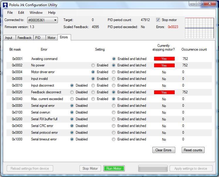
From step 1 to step 8, we had no problems. And when at step 8 we turned on the power supply for the first time the linear actuator shaft fully extended but stopped and the sotfware jrk configuration do not anymore clear the errors:
0X0001 Awaiting comand
0X0002 No power

0X0020 Feedback disconnect

And now each time we turn on the power supply the actuator dosen’t works anymore.

We took a thermal photograph of the jrk controller card with the power supply on and a component seems to warm up.

Is there a procedure to reset and test the jrk controller? Does the card controller has a problem?
Can we test the actuator without the jrk controller?

hoping that someone could help me to resolve the situation, I’ll stay waiting for ar reply.

Thanks.

upload image of errors jrk pololu controller


since it worked the first time I would guess the connections are correct but I would double check. The current draw from your supply should be pretty low but I would measure the voltage at the input terminals to make sure (and the polarity is correct).
after your voltage test are verified good, do a clear errors and reset counts. then the run motor button if the errors stay cleared

Hello.

To reset to default settings go to the “Reset to default settings” option from the File menu. However, I suspect that this will not fix the behavior you are seeing.

You mention that one of the components on the jrk is getting hot. Could you tell me which component? A picture pointing out the component might help. Could you please also tell me more about your setup? What power supply are you using and how it is connected? Could you also post pictures of your setup?

You might try testing the linear actuator by itself by connecting your power directly to the black and red leads on the linear actuator. By applying power in one direction and then the other you can extend and retract the linear actuator. You can check the feedback of the actuator as well by measuring the resistance across the blue and white (or blue and yellow) leads as the actuator extends and retracts.

  • Grant

[quote=“scotty5a”]since it worked the first time I would guess the connections are correct but I would double check. The current draw from your supply should be pretty low but I would measure the voltage at the input terminals to make sure (and the polarity is correct).
after your voltage test are verified good, do a clear errors and reset counts. then the run motor button if the errors stay cleared[/quote]

Thanks for reply Scotty5a,
but I’ve already checked the connections many times they are correct least because they are also not very complex. The current draw from my supply can range from 0 v to 24 v (it’s a laboratory power supply and it is controlled for experimental settings) and I have measured the voltage and it is correct. I made it work at 12v and at 24 v.

The clear errors don’t reset. The counts button resets but there’s no change and the run motor button seems to be always on and don’t let me stop with the “stop motor” button. I also uninstalled the software and the drivers and installed it again but it seems that the problem remains the same.


Hello Grant,
thanks for reply, I saw it this morning because here in Italy (Rome: Central European Time) there is not the same time zone as in Las Vegas.

The “Reset to default settings” option from the File menu works well and resets all, but you’re right as you suspect that this do not fix the problem.

About the component on the jrk witch is getting hot i post a thermal picture of the jrk and joined a picture of the card where I indicate (yellow circle) which component seems to get hot.

About my setup i download the jrk 21v3 settings file for use with LACTxP : jrk21v3_linear_actuator_settings.txt
(joined to the present post in attachements)
About my power supply, i put it on 24 v ( but i try also with 12 v) as showed in the 2 picture in the next post (Cannot add another attachment, 3 is the maximum) with the connection to the jrk controller. And when i get the connection on, the 24v seems to drop to 2.5 v (see pictures).
If I remove all connections to the actuator and to the usb portable computer, and leave only the power supply connected to the jrk, the votage drops too.
I read in the jrk guide that automatic motor driver shutdown on under-voltage, over-current, and over-temperature conditions. Taking into account that in any case all the checks have shown that there are no errors connections or overfeeding, is the jrk also damaged?

I tested the linear actuator by itself by connecting my power directly to the black and red leads on the linear actuator. By applying power in one direction the linear actuator which had remained extended in the first test with the jrk, now retract. But from now when applying power in the other direction nothing append and it dont extend anymore ( the voltage stays at 24 v). And reversing the power supply again I can hear the motor straining and the power supply seems to drop too (voltage drops to 2.5v) as with the jrk.( jrk controller not connected to the actuator during this test).
jrk21v3_linear_actuator_settings.txt (1.39 KB)


About my power supply, i put it on 24 v ( but i try also with 12 v) as showed in the 2 pictures joined to this post (Could not add another attachment to the last post, 3 is the maximum) with the connection to the jrk controller. And when i get the connection power supply on, the 24v seems to drop to 2.5 v (see pictures).

The part that gets hot on the jrk motor controller is the motor driver chip; if that is the part that failed, then the controller would not work and would be very difficult to repair. Were you running the jrk at 24V when it failed? If that is the case, then that is probably what caused the damage to both the linear actuator and the motor driver on the jrk. Please note, the concentric linear actuator is not rated for 24V, and the jrk 21v3 would probably not be able to handle the amount of current the actuator would draw when used at that voltage.

If you would like to try again, I might be able to get you a discount on a replacement jrk to help out. Please email us directly at support@pololu.com with you order information and I will see what I can do.

  • Grant

I also poped one of the boards I had while running the linear actuator (at 12v) but in my case the chip actually blew up… If your output driver is shorted that would explain your dilema.

My mistake was changing directions rapidly (analog input with a position pot) and I had the speed set to max (600) and not enough current limit control. I actually went back and forth probably 5-6 times before it blew up. I decided after that to go to the heaver 12v12 controllers and have been much happier with them.

I am doing life cycle test with two linear motors and I have one motor that is consistantly pulling over 4 amps, I think it has a rough spot in the main shaft gear. The 12v3’s would have never survived. The motors are working pretty hard moving 60 lbs each full stroke every 20 seconds. They’re holding up well at 1500 cycles so far, I am pretty impressed with them for their cost.

Of note, I had one motor that the feedback pot was bad. I had a pot to replace it with and it was less trouble then trying to send it back.

Hello Grant,
When running the jrk with the actuator, we start at 5 v with the power supply until we get to 12 v the voltage of the motor. And when the motor stopped suddently we try to go until 24 v thinking that the voltage was not enough to drive it.
But i don’t think that this caused the damage to the jrk because in the user guide it is said that the jrk support also 28 v operating supply:

“Main Features of the Jrk 21v3:
5 V to 28 V operating supply range
3 A maximum continuous current output (5 A peak).
Automatic motor driver shutdown on under-voltage, over-current, and over-temperature conditions.”

Was 24 v too strong to burn the chip motor control of the jrk? and the over-current protection shutdown?

I think instead that the problem came out because of the feedbacks of the linear actuator why it stopped when totaly extended and was not able to retract anymore with the jrk commands but only manualy by itself by connecting the same power used the same day directly to the black and red leads on the linear actuator.

It is not that the jrk cannot handle the voltage (the driver can handle a transient voltage up to 40V). The problem is that your actuator will draw significantly more current at 24V (as much as 20A at stall), and that sudden inrush of current could still break the jrk despite its overcurrent protection. Was there any load on your actuator while you were testing it?

- Grant

no, there was no load on the actuator while we were testing it.
It was testing free. The use in charge will be on the legs of a robot.
The research project involves the use of 3 + 3 linears actuators for each leg with as many jrk controllers to have the load on the linears motors.
it is possible that the feedback return actuator did not work and did force the actuator as if it were in charge?

Maybe I have to use a jrk 12V12 instead of the 12V3 jrk?

(Main Features of the Jrk 12v12:
6 V to 16 V operating supply range.
12 A maximum continuous current output (30 A peak).)

If the end switches were damaged, it is possible that the actuator did not know it was at the end and tried to move despite being stalled.

In regards to your controller,the jrk 21v3 should still be fine as long as you do not exceed the actuator’s rated voltage. The jrk 12v12 would be more robust as it can handle more current, but I still suspect there is something wrong in your setup from the initial behavior you described.

  • Grant

I can’t tell from your post but does your motor still drive to each end when driven straight from the ps? The built in limit switches should drop the current to 0 when it gets to the end and the internal diodes allow you to come off the switch in the reverse polarity. If it does I would measure the pot while it is moving to see that part is working too.
My driver boards don’t have any heat at all with just the power applied and motor disconnected, if it is still hot then I would still bet the driver chip has shorted out. At least you can find out if your motor is good.