Problem:
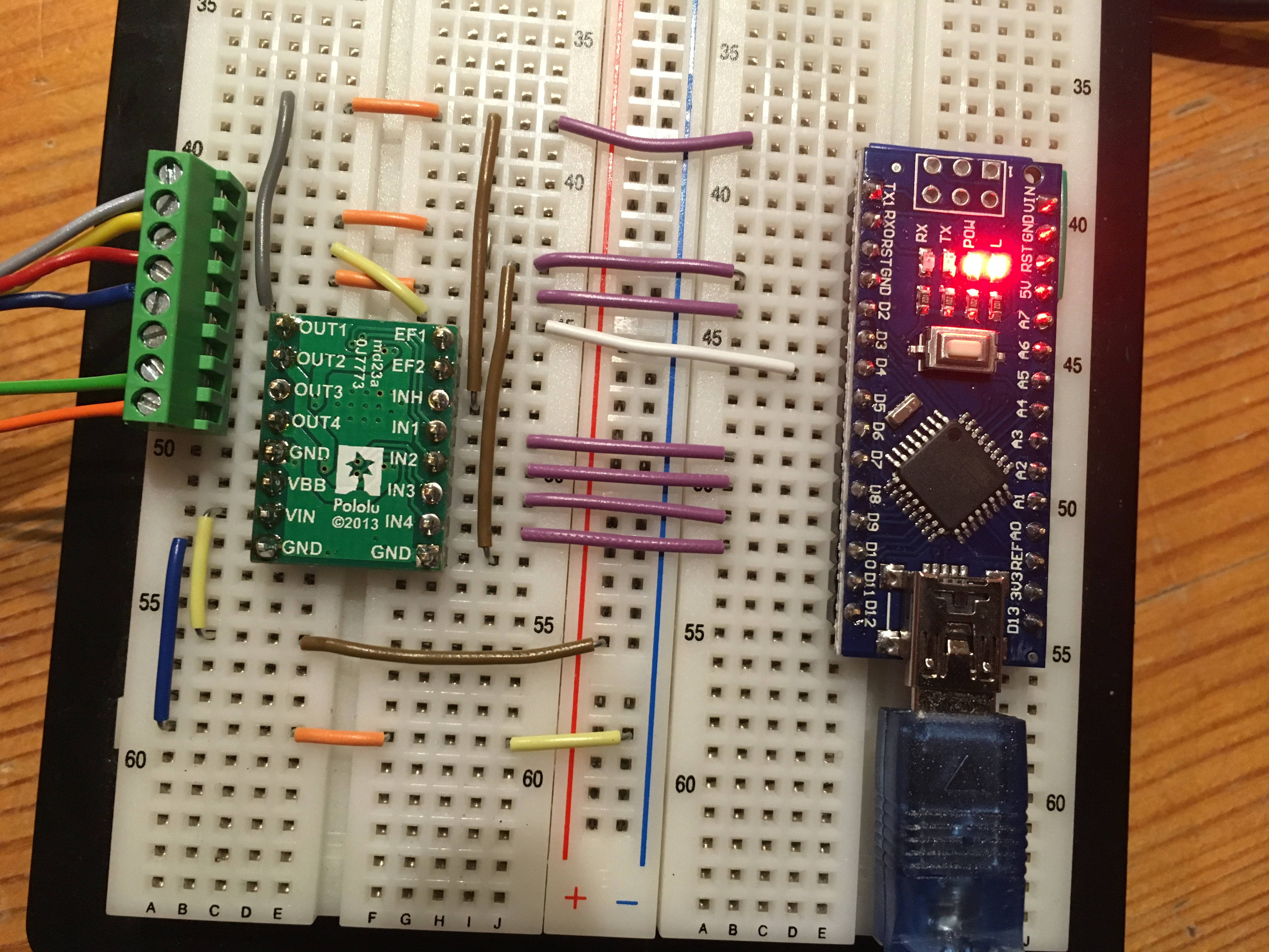
When I type in 330 as speed the motor turns just as desired, but when I type in -330 the direction does not change. If I change the pins for PWM and DIR the behavior is exactly the opposite. Please note that I am currently only trying to get Motor Output #2 to work, bothering with the other one will come later.
Does anybody have a clue why I get this strange behavior?
The A4990MotorShield library for the A4990 Dual Motor Driver Shield for Arduino cannot be used with the carrier version, because the shield has additional logic gates on its inputs (see the schematic diagram near the bottom of its product page).
We do not have any example code for the A4990 dual motor driver carrier, so you probably would need to write your own. If you do not already know, the carrier version requires four PWM signals, one for each input (IN1 through IN4), whereas the A4990 shield simply needs two PWM and two digital signals. I recommend that you first read the A4990 Dual Motor Driver Carrier’s product page, particularly the “Using the motor driver” section, and look at the motor output truth tables in the A4990 datasheet (linked under the “Resources” tab on the product page) for a clear understanding on how the inputs affect the outputs. Then, you can try writing a simple program that focuses on controlling the speed and direction of one motor channel. If you run into trouble with your code, you can post it here, and I would be happy to take a look.
Hello Amanda.
Yes it was quite naïve of me to think that the two boards would be pin-compatible without looking at the datasheet, the product page or the schematic of the shield.
However, I got the motor up and running now and it was comparably easy.
For anyone else stumbling upon this thread with a similar problem, I have now made a library which is located here: https://github.com/joelsa/a4990-dual-motor-driver-carrier and has additional support for error handling, sleep control and reading out the encoder data.
It isn’t really beautiful but it works™.
I am still somewhat unpleased that I have to use four of my precious six PWM pins on the Nano, but since I am planning to do a PCB with female headers for the driver anyway I might as well add the logic you guys included on the shield to reduce the number of PWM pins needed to two.
I have one last question left and hope that this thread is the right place for it:
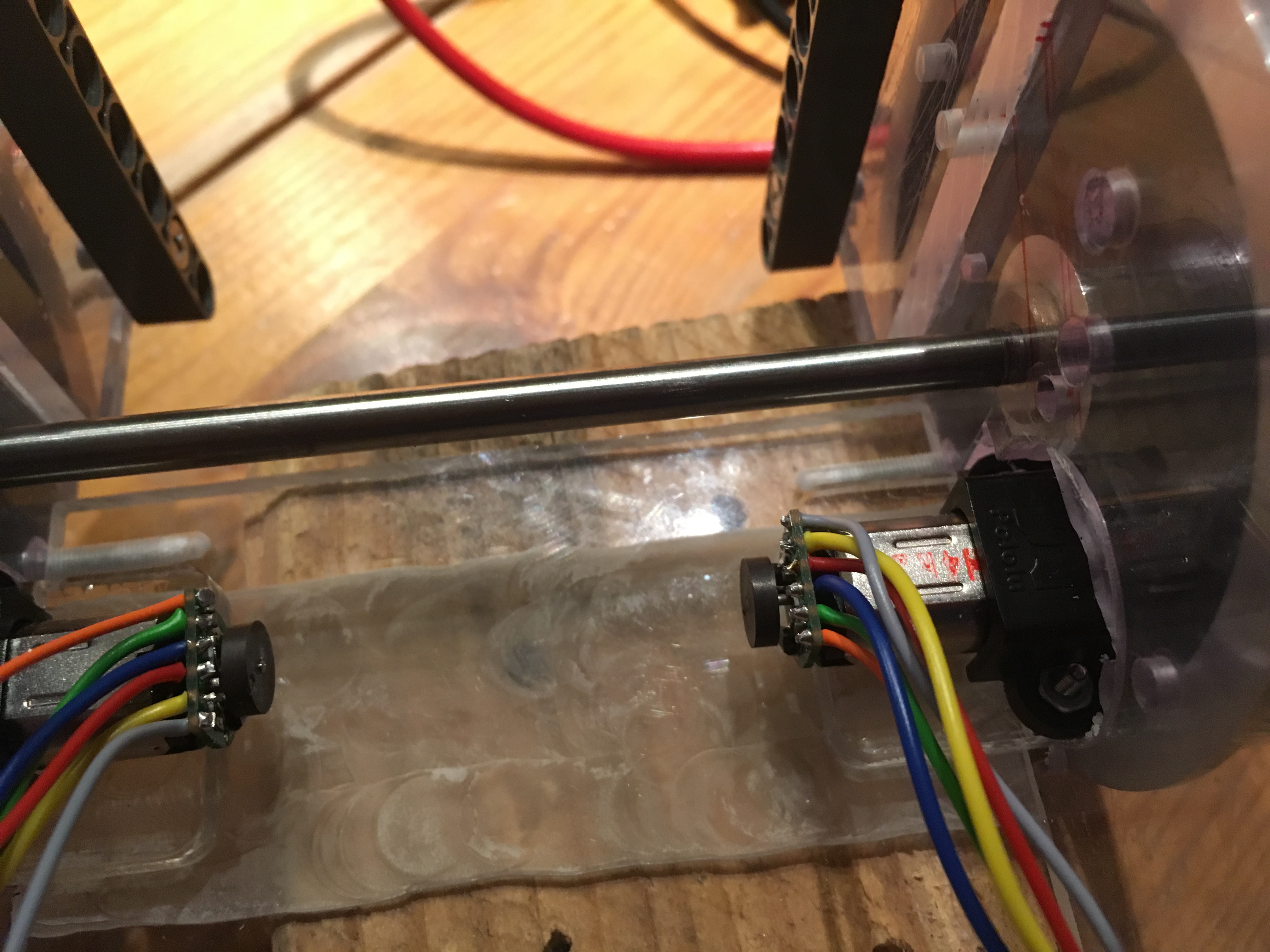
When I read out the magnetic quadrature encoder that I have sticked onto my motors, they give me 300 steps per revolution of the motor output shaft. But since there are 6 magnets on the disc I was expecting 600 steps (the ratio is (100:1). I am reading the encoder with OUTA connected to an interrupt pin and OUTB connected to a normal GPIO pin for checking the direction. Is this the expected behaviour?
I do not need such a high resolution for my application, I was just confused.
Awesome! I’m glad you got your issue resolved; thanks for sharing your library for the A4990 carrier version.
Regarding your encoder problem, it looks like you might be using our Magnetic Encoder Pair Kit from your pictures and are probably reading only one edge of the encoder signal. The magnetic disc used in that kit consists of six magnetic poles, or three north-south pairs (as stated on the magnetic encoder disc’s product page). To get the resolution you are expecting, you can read both falling and rising edges of channel A’s (OUTA) output signal. You might find the Arduino “Reading Rotary Encoders” tutorial helpful.