With my Oscilloscope i measure the pulse of my ping sensor and it was 2.41mV(here is the pulse out) and -2.41mV <-here the echo
What is the Low voltage/pulse input limit on the Orangutan-B 328?
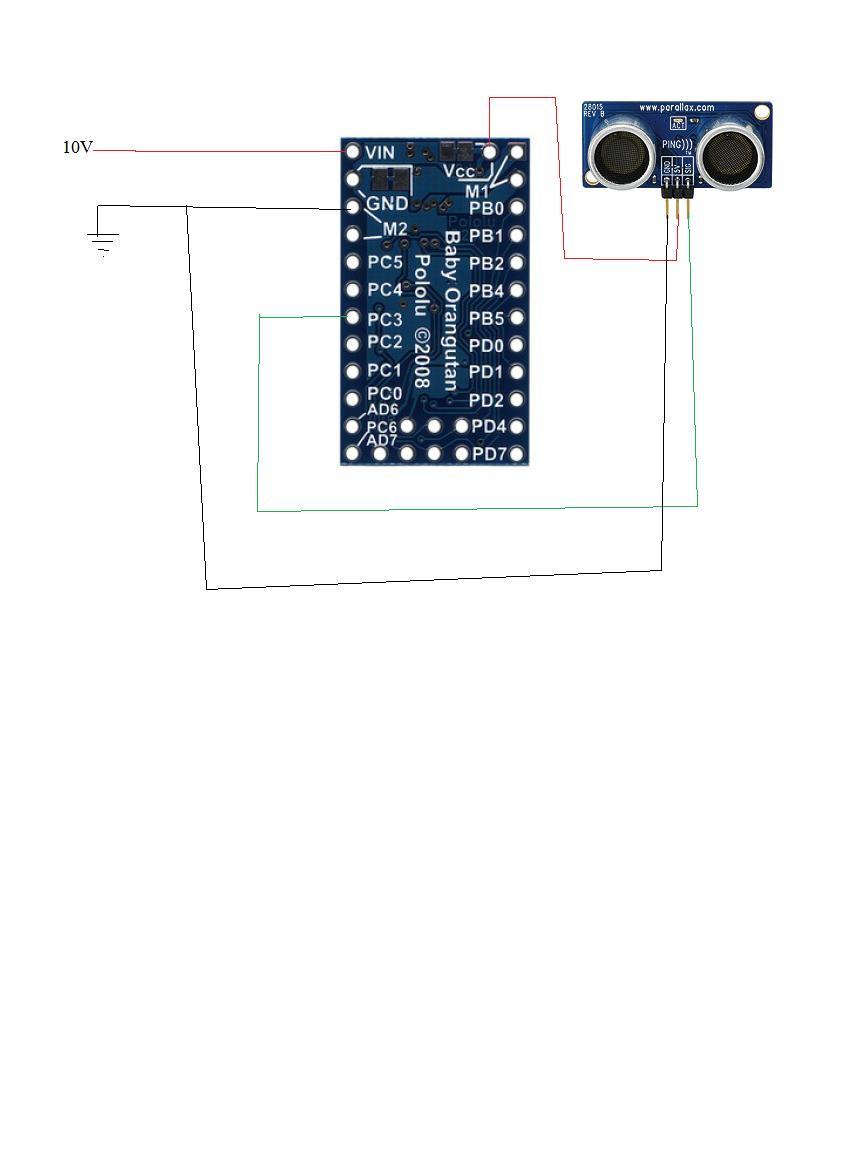
the ping sensor is hooked in pin IO_C3
Is there away to increase the voltages in the code?
It is not storing the pulse in ( LastHighPulseMicroseconds).
my arduino(mini and uno) gives me much higher pulses. I used this as my comparison for the baby orangutan-B 328.
I was thinking it was something to do with Baby Orangutan-B 328, instead of the code.
Are you using an actual Parallax Ping))) sensor or some other sonar sensor? If the sensor is only outputting a few millivolts, then you are likely either not using it correctly, not measuring it correctly, or it is damaged. The guaranteed-high threshold for the Baby Orangutan digital inputs is 3 V. Can you explain your setup in detail and possibly include a picture? Also, can you simplify your program to the shortest thing that should work but doesn’t, and can you clean it up so that commented-out lines are removed and the remaining lines are properly indented? It is very difficult to read your code as you posted it.
I put 1x (the oscilloscope set 1x probe) probe to Sig and ground to ground(- rail).
I would like to talk about my Baby orangutan B 328. I believe my problem lies with output of the device to trigger a good response out of the ping sensor. But instead the trigger pulse give me 5V. The end results is that i have an echo pulse of 1.81V , instead of the 3.3v or 5v.
Compared to my Arduino mini . Arduino gave me an output of 32v and the Arduino mini is power by usb port. when i connect it the Ultrasonic ping sensor i get a response out of the Arduino mini. the Echo pulse Vp is small then the trigger pulse. But it worked.
I almost convinced that i damaged the input, when i started to use it the very first time. When i accidentally hooked in power supply to ad6 ad7. this made the Microprocessor got hot and maybe ruined some transistor inside. (didn’t smoke)
Whoops
should I buy a new Orangutan-B 328 because of this mistake?
Connecting power to the I/O lines on the Baby Orangutan can definitely break the microcontroller (it’s getting hot is also a bad sign). If you email us with your order information and refer to this thread, we might be able to get you a discount on a replacement.
It’s fine. I that pololu won’t give a discount for a new baby Orangutan b 328 do to an accident. so I already order a new one.
I was wondering if I can solder pins to the board in a way that the white letters are facing up? the reason is to know actly what pin PC3…
If you solder the board in that orientation, the 6-pin programming header will not match the cable from your programmer, and I think it would be a pain for you to try to make a new cable that would work. We just added a printable pin assignment diagram that might make it easier for you to identify which pin is which: