
hii there, i have arduino uno and VNH5019
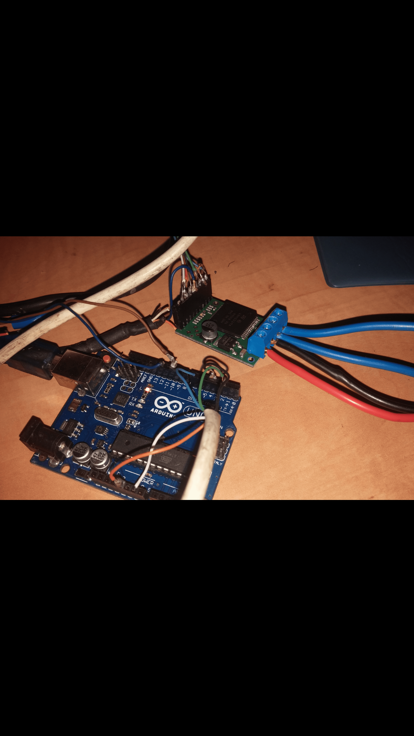
i not sure it is a problem with the code or the connection. i put the pins like this picture
and no matter what pins i put HIGH\LOW in the code the motor is always spining.
can some send me an example code or something i didn’t find any.
Hello.
We do not have any code examples written for the VNH5019 Motor Driver Carrier. Can you post your entire code here so that I can see if there is anything obviously wrong with your code? Also, can you post close-up pictures of your setup that show all your connections and both sides of the motor driver board? What motor are you using? A link to the motor’s datasheet or product page would be helpful.
- Amanda
a 24v 14a motor
i put the ENA,ENB,PWN,INA,INB in the DIGITAL pins of the arduino and
declare them on setup and on the VOID LOOP set all of them at LOW
It is difficult for me to help you troubleshoot the issue without more information. Again, can you post your entire code and pictures of your setup that show all your connections and both sides of the motor driver board here? Also, what power supply are you using?
- Amanda
connections:
motor drive arduino
GND GND
VDD 5V
INB 4
INA 6
PWN 2
ENA 10
ENB 12
code:
#define pwn 2
#define inb 4
#define ina 6
#define ena 10
#define enb 12
void setup(){
pinMode(pwn,OUTPUT);
pinMode(inb,OUTPUT);
pinMode(ina,OUTPUT);
pinMode(ena,OUTPUT);
pinMode(enb,OUTPUT);
}
void loop(){
digitalWrite(pwn,LOW);
digitalWrite(inb,LOW);
digitalWrite(ina,LOW);
digitalWrite(ena,LOW);
digitalWrite(enb,LOW);
}
now no matter how i change it(LOW\HIGH) the motor is always spinnig.
i am using two 12V 12A battry connect toghther.
We generally do not recommend using the VNH5019 motor driver carrier with 24V batteries, since it could trigger the overvoltage protection on the motor driver. You can find that warning on the VNH5019’s product page and should consider running the motor at a lower voltage or getting a motor driver that can handle 24V.
I did not see anything wrong with your code, but I do not suspect that your code is causing the issue that you are seeing. Again, can you post the pictures that I requested previously?
- Amanda
arduino :--------drive:
green (2)--------PWN
black (4)--------INB
azure (6)--------INA
brown (10)-------ENA
blue (12)---------ENB
white (GND)-------GND
orange(5V)---------VDD
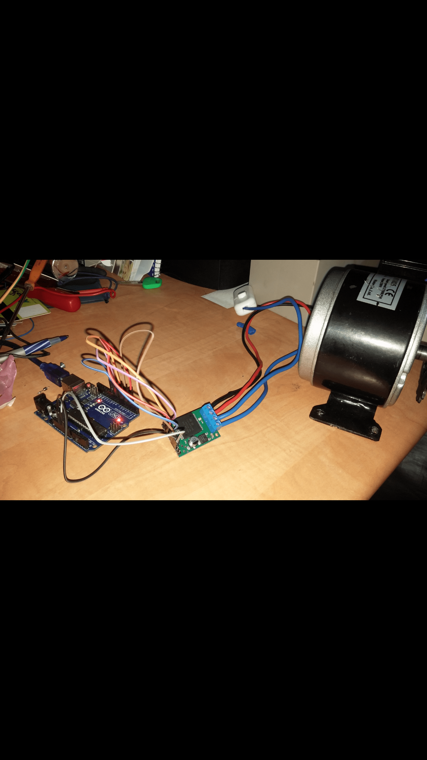
on the drive the two blue wire OUTA,OUTB goes to +- on battery
From your description, it sounds like your leads are swapped and the power connection are connected to OUTA and OUTB of the VHN5019 motor driver, so it is possible that you may have damaged the motor driver. You should try connecting your power source to VIN and GND and motor connections to OUTA and OUTB to see if the motor driver still works.
As for your connections, it is difficult to see how the wires are connected to the motor driver board from your picture. If you have a multimeter, I strongly recommend checking for continuity between the wire and the associated header pin on the board to make sure the wires are making good contact.
Also, your soldering joints look very suspect, which could cause problems (e.g. short) in your setup. This Adafruit soldering guide has good references for what the solder joints should look like and tips on how to solder. Instead of redoing the solder, an easier and cleaner method would be to use wires with pre-crimped terminals and crimp connector housings. You can watch the “Pololu Cables and Wires” video at the top of the Cables and Wire page to see how fast and easy it is to make your own custom cables.
- Amanda
#define pwn 2
#define inb 4
#define ina 6
#define ena 8
#define enb 10
void setup(){
pinMode(pwn,OUTPUT);
pinMode(inb,OUTPUT);
pinMode(ina,OUTPUT);
pinMode(ena,OUTPUT);
pinMode(enb,OUTPUT);
}
void loop(){
digitalWrite(pwn,HIGH);
digitalWrite(inb,HIGH);
digitalWrite(ina,LOW);
digitalWrite(ena,LOW);
digitalWrite(enb,HIGH);
}
i swap the power and motor wires, change the code and switch to good cables, now the motor doesn’t spinning.
From your code, it looks like you are setting the VNH5019’s ENA pin low and ENB pin high. Those pins need to be pulled high to enable the chip. For more details, see the “Waveforms and truth table” table in the VNH5019’s datasheet under the “Resources” tab on its product page. Also, pin 2 on the Arduino Uno does not output PWM signals, so you probably will need to change that pin if you want to control the motor’s speed.
After making those modification to your code, can you try running your motor at 12V instead of 24V by supplying VIN and GND with 12V? That way we can make sure that the overvoltage protection is not triggering while testing the modified code.
- Amanda