Problem: Motor A wont start until 128 PWM (Using: TB6612FNG)

Hi,

I’m having trouble with my Motor driver, I’m using TB6612FNG.

I’m constructing a line following robot, using two motors and a dual motor driver who takes in PWM values and a reflection sensor.

This is how the setup looks like:

The setup is as simple as possible, driver inputs are connected from 0-6 and reflection sensor from 7-13.
The arduino and motor are supplied by two different batteries; both 9 V.
I’m using the same 5 V form the arduino for logic power of both the reflection sensor and the motor driver.
Sensor works fine! but the problem is that motor A does not start until the PWM value is 128. Motor B works fine!

What I’ve tried:
I’ve tried connection both motors to AOUT(A01 and A02) so the problem is clearly in the motor driver(not the motor).
I’ve tried velding the vires better to the driver.
I’ve tried a lot of different programs so the coding doesn’t seem to be the problem.

Could there be some connection problems? Or is it broken?
I’ve heard about other people have this problem but I didn’t see any solution to this problem.

In hope of quick responses,
Steinidna.

Hello.

It looks like Sparkfun’s TB6612-based motor driver, not ours, so I have moved this thread to our general electronics forum. I think the problem is unlikely to be with the driver. 9V batteries are not suitable for driving motors; can you see if using a more appropriate power supply makes the problem go away?

If not, can you tell me exactly how you have everything connected and post the simplest program that demonstrates the problem? At what speed does the other motor B start turning? By the way, what is the stall current of your motors?

- Ben

Here’s an example of a program that we ran:

#define PWMA 0
#define AIN1 2
#define AIN2 1
#define BIN1 4
#define BIN2 5
#define PWMB 6
#define STBY 3
#define motor_A 0
#define motor_B 1
#define FORWARD 1
#define REVERSE 0
#define RIGHT 1
#define LEFT 0

void setup()
{
  pinMode(PWMA,OUTPUT);
  pinMode(AIN1,OUTPUT);
  pinMode(AIN2,OUTPUT);
  pinMode(PWMB,OUTPUT);
  pinMode(BIN1,OUTPUT);
  pinMode(BIN2,OUTPUT);
  pinMode(STBY,OUTPUT);
  
  motor_standby(false);        //Must set STBY pin to HIGH in order to move
}

void loop()
{
  motor_brake();               //STOP for 1s
  delay(1000);
  motor_drive(FORWARD, 150);   //Move FORWARD at full speed for 1s
  delay(1000);
  motor_brake();               //STOP for 1s
  delay(1000);
  motor_drive(REVERSE, 150);   //REVERSE at about half-speed for 1s
  delay(1000);
  motor_brake();               //STOP for 1s
  delay(1000);
  motor_turn(RIGHT, 150, 150); //Spin RIGHT for 0.5s
  delay(1000);
  motor_brake();
  delay(100000000);
  }

//Turns off the outputs of the Motor Driver when true
void motor_standby(char standby)
{
  if (standby == true) digitalWrite(STBY,LOW);
  else digitalWrite(STBY,HIGH);
}

//Stops the motors from spinning and locks the wheels
void motor_brake()
{
  digitalWrite(AIN1,1);
  digitalWrite(AIN2,1);
  digitalWrite(PWMA,LOW);
  digitalWrite(BIN1,1);
  digitalWrite(BIN2,1);
  digitalWrite(PWMB,LOW);
} 

//Controls the direction the motors turn, speed from 0(off) to 255(full speed)
void motor_drive(char direction, unsigned char speed)
{
  if (direction == FORWARD)
  {
    motor_control(motor_A, FORWARD, speed);
    motor_control(motor_B, FORWARD, speed);
  }
  else
  {
    motor_control(motor_A, REVERSE, speed);
    motor_control(motor_B, REVERSE, speed);
  }
}

//You can control the turn radius by specifying the speed of each motor
//Set both to 255 for it to spin in place
void motor_turn(char direction, unsigned char speed_A, unsigned char speed_B )
{
  if (direction == RIGHT)
  {
    motor_control(motor_A, REVERSE, speed_A);
    motor_control(motor_B, FORWARD, speed_B);
  }
  else
  {
    motor_control(motor_A, FORWARD, speed_A);
    motor_control(motor_B, REVERSE, speed_B);
  }
}

void motor_control(char motor, char direction, unsigned char speed)
{ 
  if (motor == motor_A)
  {
    if (direction == FORWARD)
    {
      digitalWrite(AIN1,HIGH);
      digitalWrite(AIN2,LOW);
    } 
    else 
    {
      digitalWrite(AIN1,LOW);
      digitalWrite(AIN2,HIGH);
    }
    analogWrite(PWMA,speed);
  }
  else
  {
    if (direction == FORWARD)  //Notice how the direction is reversed for motor_B
    {                          //This is because they are placed on opposite sides so
      digitalWrite(BIN1,LOW);  //to go FORWARD, motor_A spins CW and motor_B spins CCW
      digitalWrite(BIN2,HIGH);
    }
    else
    {
      digitalWrite(BIN1,HIGH);
      digitalWrite(BIN2,LOW);
    }
    analogWrite(PWMB,speed);
  }
}

In this case both motors turn fine with 150 PWM.

If we change the code to: motor_drive(FORWARD, 120) or motor_turn(RIGHT, 120, 120)
Then only motor B will turn.

If we change the code to: motor_drive(FORWARD, 130) or motor_turn(RIGHT, 130, 130)
Then both motors will turn, and motor A will go according to 130 PWM.

It seems to be around 128 PWM that it suddenly starts turning.

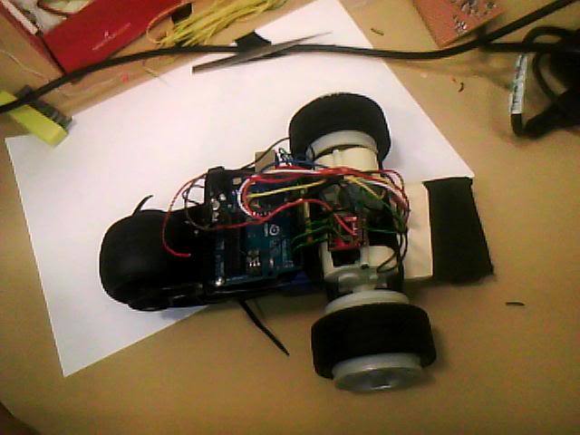
It is connected as follows:

The arduino is powered by a 9V in Vin and GND.
Outputs 0-6 on the arduino go in the motor driver.

The logic on the motor driver is powered by 5V from the arduino.
The other 9V is then connected to Vm and GND on the motor driver(does it matter what GND?)
The motors are connected to A01,A02,B01 and B02 on the driver.
Then we have two GND left on the driver that are connected together and into GND on the arduino.

I’ve tried another power supply and we still had the same problem.
I measured the stall current for the motors and it is 300mA.

Thank you for the reply!

I just ran the following code from the program:

void loop()
{
  motor_brake();               
  delay(1000);
  motor_drive(FORWARD, 50);  
  delay(1000);
  motor_drive(FORWARD, 75); 
  delay(1000);
  motor_drive(FORWARD, 100);  
  delay(1000);
  motor_drive(FORWARD, 125);  
  delay(1000);
  motor_drive(FORWARD, 150);  
  delay(1000);
  motor_drive(FORWARD, 175);  
  delay(1000);
  motor_drive(FORWARD, 200);  
  delay(1000);
  motor_drive(FORWARD, 255);  
  delay(1000);

I measured the voltage output over A01 and A02, and B01 and B02.
For the working one(B) the voltage measured increrasing from 1-7.8 as expected.
But for output A it suddenly kicked in at the timing of the 150 PMW at full voltage output! (7.8 V)

It looks like at 127 it kicks in at full duty (exactly half of 255, full duty?).

EDIT:
I tried to make motor A go in reverse to see if there was a problem with just A01,
when I ran the program in reverse the it kicks in at under 50 PWM at full duty.

I didn’t read most of what you wrote yet, but I’m pretty sure I know what your problem is: you are not using a PWM output for PWMA. The analogWrite() function only works properly with the AVR’s six PWM outputs. For all other pins, it just works like digitalWrite(): the line is high 100% of the time when the specified duty cycle is 128 - 255, else it is low 100% of the time. If you use pin 5, things should work as expected.

- Ben

Thank u kind sir, we changed it to pin 3. All works smooth now.

I’m glad to hear it’s working for you now, but I still think that pin 5 is better than pin 3. Otherwise, your two motors will be running at two different PWM frequencies, which could lead to subtle differences between the two motors.

- Ben