Powering 3 micro stepping pumps simultaneously

I am currently working on a project that requires me to use 3 micro stepping motors that act as a peristaltic pump. I have no access to the data sheet, but the company we purchased them from has provided the seemingly crucial information which I will include below. The microcontroller is an ESP32 dev kit c4, and I am using 3 STSPIN220 breakout module from Pololu for the drivers.

The goal of the project is to control 3 pumps simultaneously, I am currently using a modification of the AccelStepper Library, that I have created for readability, in order to accomplish this task. The software is functional, however I am having trouble with the circuit design.

Currently, running any one driver board/ stepper, everything works fine. The motors function as expected and different rpms can be achieved. However, when I run 3 motors simultaneously, I get sporadic results. Sometimes all three will run and then 2 will randomly stop. Maybe two will run, and one will not. Nothing is consistent.

I have included two schematics, one is a breakdown of just the 3 driver boards, esp32, and how they receive their power. The other one(which has had some modifications on the pin inputs to the driver boards) is the schematic of the full project. It contains a few more parts that I do not think play a role in the current issue, but I have included it just incase. Additionally I am running it off a decent quality bench power supply at the moment.

After many other suggestions, I decided to try out a different driver. This way I can provide a magnitude more of voltage to the motor, in order to ensure I can provide the necessary current on time for all three drivers. This time I choseTMC2209 from watterott, as hopefully I can mitigate wiring using uart in the future. However, this has given me identical results. I can drive one motor fine, but when I try and drive three, I run into issues.

I’m inclined to believe that the issue is hardware related, and I am missing an essential component in filtering either signal/power lines headed to/from the driver.

Any and all suggestion help! Thanks in advance!

Stepper Motor Specs:

  • Inductance Rating: 2.2mH (REF. At 25C 1KHz,1.0Vrms (Each phase))
  • Rated Voltage: 2.6VDC
  • Rated Current: around 200mA at 2.6VDC
  • Type: 2-2 Phase exciting, bi-polar stepper motor
  • Step angle: 0.349880 degrees
  • Speed reduction ratio: 1:51.4462
  • Pump can rotate: CW or CCW, but make sure the pump is completely stopped for 2-3 sec before changing the rotation direction.
  • Resistance: 21 ohms +/-5% (at 25C)
  • Max starting pulse rate: 800pps/min (constant voltage, no load)
  • Max constant pulse rate: 1000pps/min (same as above)
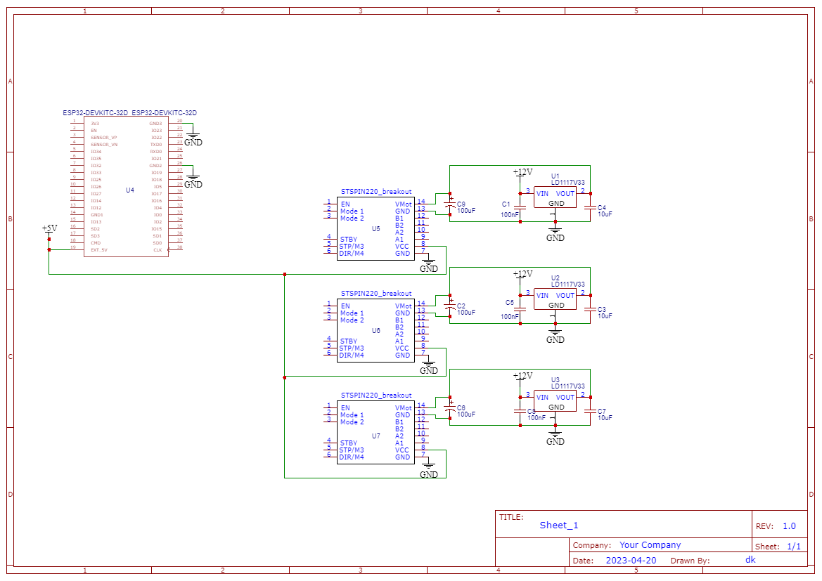
Schematics:

Simplified Partial Schematic:

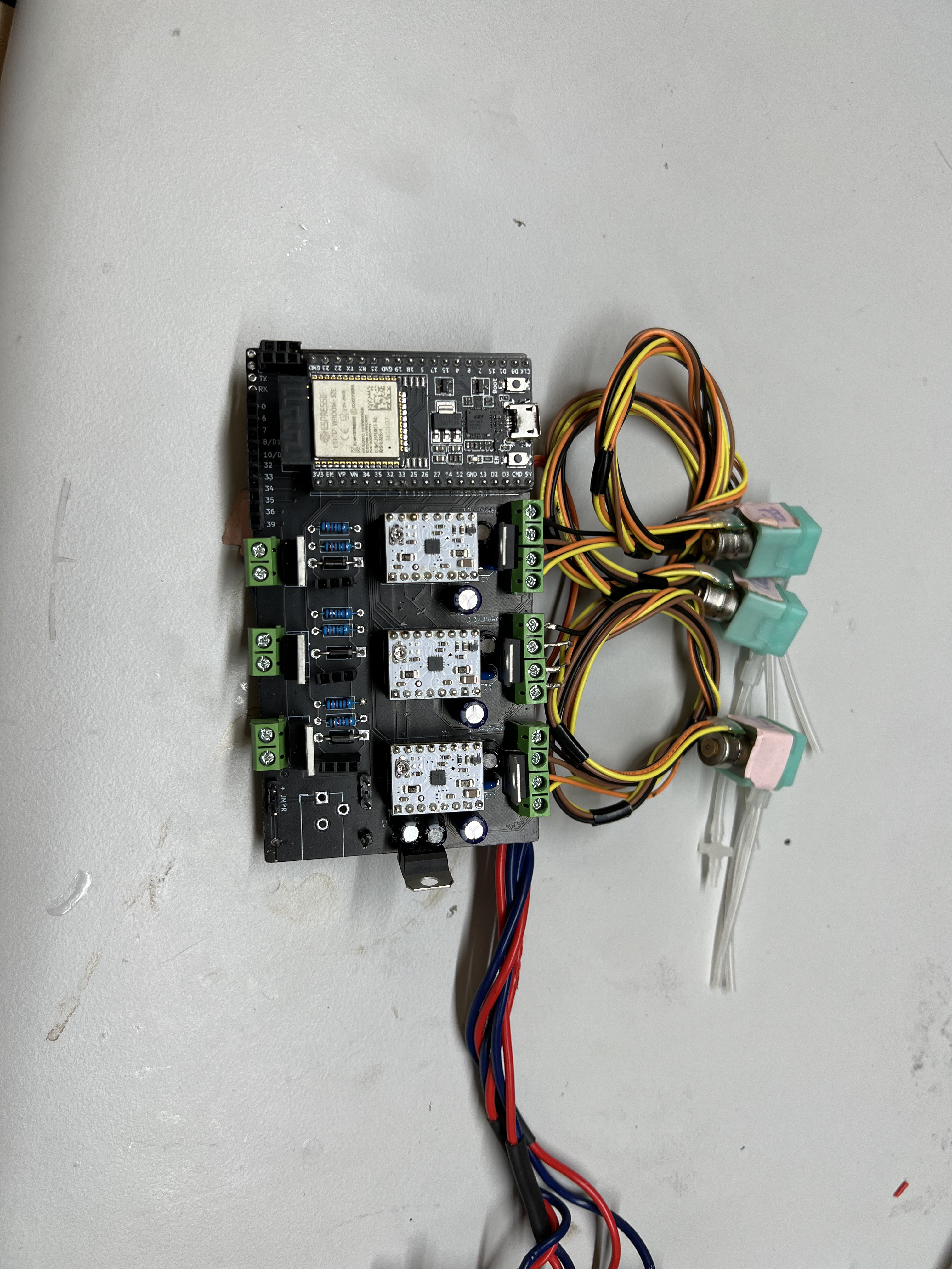
PCB board (Full design - PCB board designed with a few other components):

Hello.

Can you post some pictures of your setup that show all of your physical connections and let me know what the VREF voltage is on your STSPIN220 boards? Just to rule our the possibility of power issues, can you confirm that the output voltage from your bench top supply is stable, and that there are no indications that a current limit is being tripped?

If there is no indication of a power issue, then my next suggestion is to look at your control signals with an oscilloscope to see what is going on. It is possible that the stepper motor power, or some other part of your system, is interfering with the control signals. However, another possibility is that your program is not working on the microcontroller as expected. Though I am not familiar with the AccelStepper library in detail to know how it handles this, in general, generating several different step signals with a microcontroller can be tricky. With that in mind, you might try looking at the control signals from your microcontroller while it is disconnected from the drivers and the rest of your system to see if they are behaving as expected.

- Patrick

Hey Patrick,

The schematics posted were used to create a pcb board, as I wasn’t sure if loose wires from the bread board was causing an issue.

As for the VREF voltage on the STSPIN220boards, they are set to 40mV. Which seem to do a decent job when running a single motor. No issues on stalling, and no overheating of the motors.

As for the bench PSU, it seems stable. I estimated the current draw of my system to be about 1.2A before some of the mods I made, and set the PSU to have a current limit of 1.6A. It never seems to go above 1.1A though. I assume that having the limit set higher, if for somereason the current draw is “requested”, than the PSU could supply it. (I may be totally wrong about that though).

I will take another look at the control signals leading into the board, they seemed to be creating consistent waveforms on all the step pins.

As for the code, I started with the AccelStepper library as it had an easy and intuitive way of running motors in parallel. However, to ensure it wasn’t a coding fault, I have tried a few different methods. One method was the simple stepping method of using a for loop and a delay. I would trigger all three pins high first, delay, then trigger all low. The other method I tried was doing the same for loop method but driving one pin high and low. This pin is then split in parallel to the three drivers. All methods have resulted in the same functionality. Working on just one board, but if three are enabled, no luck. This has lead me to believing that it is a problem somewhere on my hardware design.

  • Dave

Could you post the simplest complete program that demonstrates the problem when all three drivers are connected? Then, please post scope captures of your system while that code is running. In particular, the main supply line, the supply voltage to each driver (i.e. VMOT for each driver), and the step signals would probably the best things to look at first.

- Patrick