Hello.
Some tips for minimizing your Wixel’s power consumption:
You’ll definitely need to turn off the radio and any other peripherals that consume a lot of power. The radio_mac library does not support turning off the radio; if you could modify it to do so, that would be great! But alternatively you could avoid using radio_mac: I think the test_radio_signal_tx app would be a good starting point for the app you run on your sensor nodes, and the radio_sniffer app would be a good starting point for the app you run at the receiver.
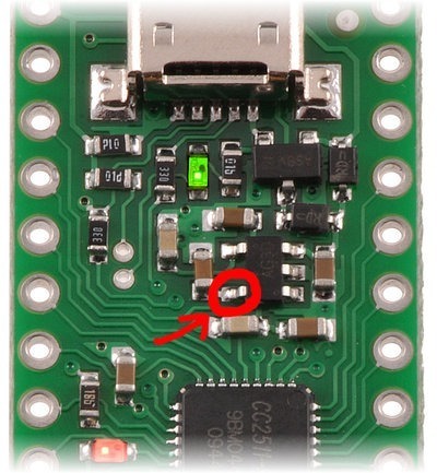
We found that the Wixel’s 3.3 V regulator wastes 40-80 microamps if either its input or its output is exposed to power. You said you weren’t too concerned about that, but if you are then you can sever the output pin of the regulator (pin 5, the lower left pin if the USB connector is facing up, shown in the picture below) and power the board directly from the 3V3 line with a 2.0-3.6 V source. You will not be able to easily power the Wixel from USB after this modification.

Another way to save power is to make sure that none of the I/O lines are at some intermediate voltage. They should either be 0 V or VDD, but not in between. By default, all the pins on port 0 and port 1 except P1_0 and P1_1 are inputs with pull-ups enabled, so they are OK (you don’t have to set those pins to outputs). P1_0 and P1_1 do NOT have pull-up or pull-down resistors, so you will want to set those to be outputs. As for Port 2, the default Wixel libraries take care of enabling pull-downs on the yellow and red LED lines so you won’t have to worry about those. But the VBUS_IN (P2_4) line and the P2_0 line are allowed to float to intermediate voltages when USB is not connected, so you’ll want to do something with those lines. I enabled a pull-down on P2_4 and drove P2_0 high in the code below, but there might be other ways to take care of them.
I think the power savings you can get by managing those IO lines correctly is around 5-20 microamps, but I forget exactly how much. It was small compared to the savings we got by severing the regulator, so if you don’t sever the regulator than it might not be worth it to you.
Finally, to minimize the power consumption of the CPU, we put it in to sleep mode 2 (the deepest sleep mode where the chip can still wake itself up). Here is the test code I wrote to set up the I/O lines and go to sleep:
#include <wixel.h>
void main()
{
    P2INP = 0b10001000;
    P0INP = 0;
    P1INP = 0;
    P1 = 0;
    P1DIR |= 3;
    P2_0 = 1;
    P2DIR |= 1;
    while(1)
    {
        SLEEP = (SLEEP & ~3) | 2;    // SLEEP.MODE = 2 : Selects Power Mode 2 (PM2).
        __asm nop __endasm; __asm nop __endasm; __asm nop __endasm;
        if (SLEEP & 3)
        {
            PCON |= 1;    // PCON.IDLE = 1 : Actually go to sleep.
        }
    }
}
By doing all of this we were able to get the current consumption of the Wixel down to 0.5 microamps, just like the CC2511 datasheet claimed.
Sensor Power Control
The P1_0 and P1_1 lines on the Wixel are special high-current lines that are designed to deliver up to 20 mA each, so it would be easiest if you can just power your sensors directly from one or two of those lines. You probably shouldn’t connect the lines together because that increases the risk of a short circuit, but if each Wixel had multiple sensors you could power some of the sensors from P1_0 and some from P1_1.
If you have a sensor that draws more than 20 mA you can use a Wixel I/O line to control a MOSFET that supplies power to the sensor.
The Pololu Pushbutton Power Switches are intended for applications where the power is controlled manually by a human.
I’m glad you are going to fork the wixel-sdk. We’ll definitely take a look at the changes you make and consider pulling it in to the wixel-sdk. Even if we don’t, the code you come up with will probably be useful for other Wixel users, so I’m glad it will be online. Thanks!
–David

