Please help,
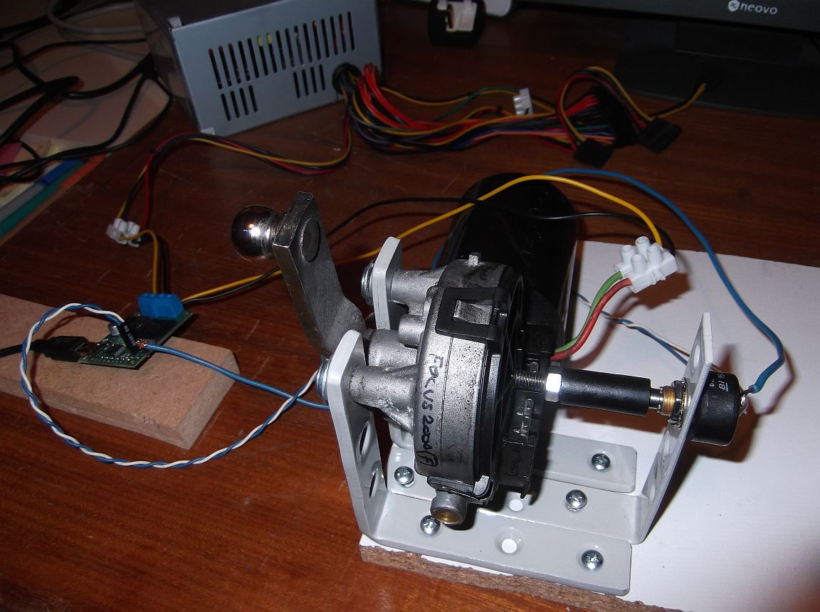
I have a Jrk 12v12 wired with usual Vin, GND, A, B to 12v motor
and a Halls sensor (spec attached) attached on the end of motor spindle.
I was recommended this sensor by several users who say it works well.
wired 5v to AUX, 5v to 5v, GND to GND
All settings are default except I enable first 6 Error checking. All errors clear and controller shows both yellow and green flashing.
Run Jrk config, On Feedback tab, I have left Analog samples at 128, if I enable “Detect disconnect with AUX”, get error flagged on feedback disconnect, so I disabled “detect disconnect”.
I run “Learn” and twist the sensor and calibration readings change.
I goto Motor tab, run “Detect motor direction” after warning I get “Centre the motor” I twist potentiometer and click OK, but this keeps coming back.
Switch everything off, reset back to default + error enables, try again without running Learn feedback (so still set at full limits) and motor runs (and turns potentiometer) hurry, but then I get error “check your motor and feedback connections”
If select green “run motor” button, changes to red stop motor, but nothing happens and no error.
These connections do not make sense to me. The potentiometer looks like it has three connection points (GND, +5V, and VOUT). The GND pin should go to any GND pin on the jrk. The +5V can go to the AUX pin on the jrk, and the VOUT pin should go to the FB pin on the jrk.
If changing the connections does not seem to help, could you post pictures of your system that show all of your connections? Also, could you post your jrk settings file? You can save the jrk settings file by choosing the “Save Settings File…” option from the “File” drop-down menu within the Jrk Configuration Utility.
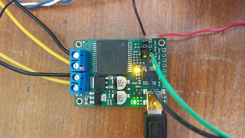
I attach picture of connections (pot end wires are soldered)
Blue is GND, blue/white is 5v/Vout, yellow & black 12v and USB
Settings file attached (after doing Feedback learn).
The motor is a Worm drive, so the motor spins quickly to turn the spindle & potentiometer slowly, is this the problem, do I need to tell Jrk this somehow ? learn.txt (1.38 KB)
Thank you for the settings file and picture. The gear reduction on the motor output should not matter; the jrk is looking at the potentiometer reading, so it should not matter how much it needs to run the motor to reach the target.
It is hard to see from the picture if your potentiometer is connected correctly. From your settings file, it looks like the maximum and minimum feedback values are both the same, indicating that the reading from the potentiometer is not changing. How is the blue ground wire connected to the jrk? Could you try removing the potentiometer from your system and testing it separately to make sure the output voltage goes from 0V to 5V when it is turned from one extreme to the other?
Thank you
I assume, I measure 0 to 5v between GND and Vout
If so, potentiometer must have fault as it stays at 2.68v, even when turn.
I have 2, so I will test other pot.
Okay so both pots work the same.
So I contacted the manufacturer and I connected an 5v and GND outside source to Pot,
with only Vout to Jrk. Volts now change when turning pot - hurry, so pot working.
I can do “Learn” feedback min & max are differnet. see config file attached.
“Detect motor direction” and motor moves very small move, then error “motor is inverted”
I apply setting with motor inverted, and run again, small move and error “motor is inverted”
again change back. Done this many times sometimes get same before "centre motor and I move pot and this message goes away now.
Select green “run motor” and stop changes to red, but still motor does not move.
If I set feedback to None, Select green “run motor” and stop changes to red, but still motor does not move.
I’ve now spent days on this, can someone post a working config
Anyone suggest something
or should I give up and send back as faulty ?
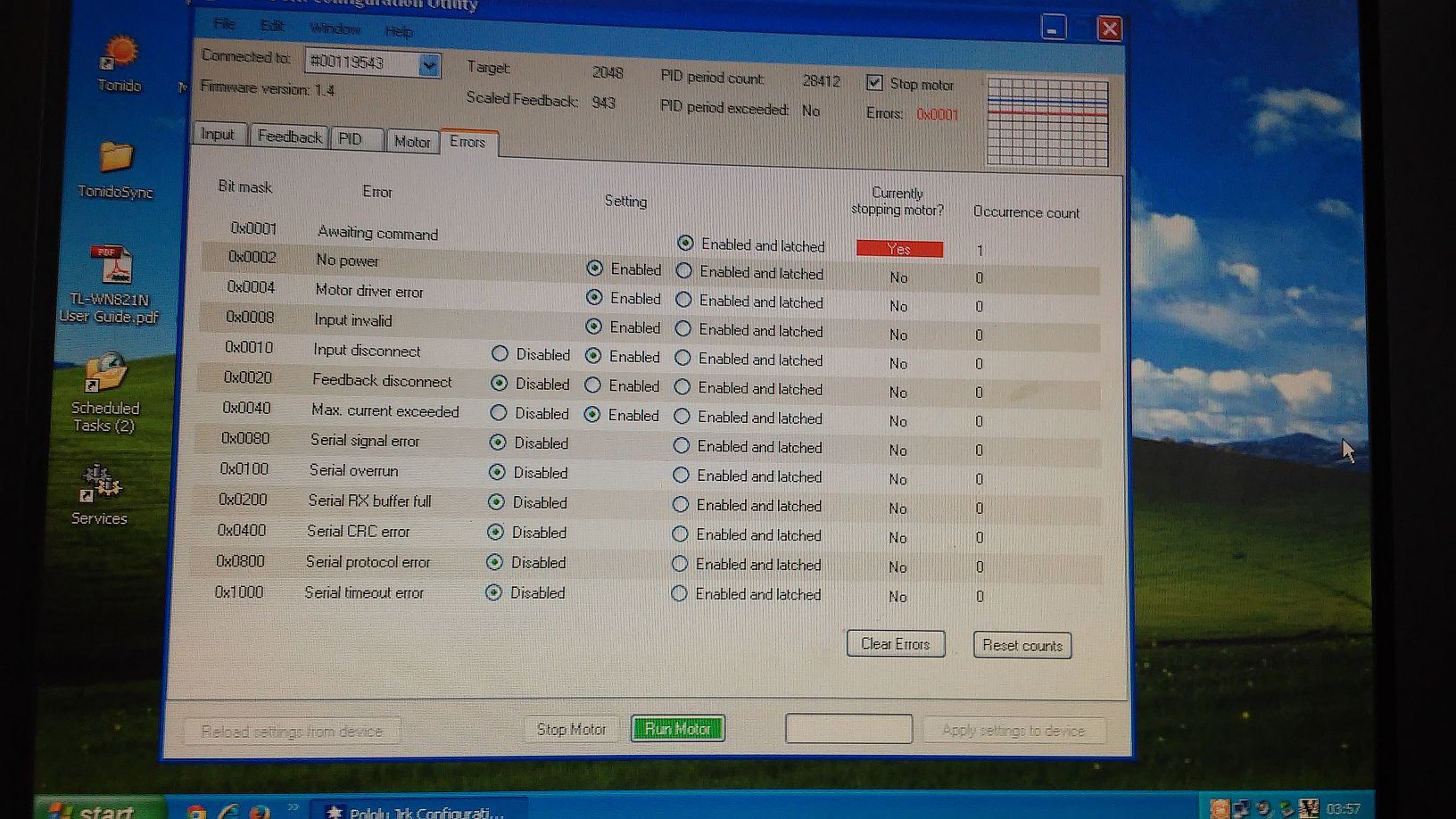
Thank you for the extra information and pictures. There are several things going on at once here that could make it difficult to troubleshoot. To start, could you disconnect everything from the jrk, connect it to your computer via USB, and set the feedback to “None”? You will likely get a “No power” and “Awaiting command” error. Once you connect your power supply back to the jrk, the “No power” error should go away, leaving just the “Awaiting command” error. Clicking the green “Run Motor” button (with the motor still disconnected) should clear that error, and no errors should be stopping the motor in the “Errors” tab of the Jrk Configuration Utility (the red LED on the jrk should also turn off at this point).
Can you try the procedure described above and see if your results are the same? If they are, could you try powering down the system, connecting the motor, and moving the “Manually set target” slider in the “Input” tab of the Jrk Configuration Utility? Please note that you will either have to click the “Set Target” button to input the change to the target, or select the “Automatically set target” option under the slider.
If you run into an error at some point in this procedure, you can check what it is in the “Errors” tab and let me know what it is and when it occurred.
Now that it is working without feedback, you should be able to add your potentiometer output to the FB pin and change the feedback mode to “Analog voltage”. You might find the instructions in the “Setting Up Your System” section of the jrk user’s guide helpful. As stated in the “Calibrating feedback” heading of that section, once your feedback is added, you can click the “Learn…” button and follow the instructions in the pop-up window. You should now have your feedback potentiometer connected to your motor.
Since you are using feedback now, you will also need to configure the PID coefficients. By default, these are all set to 0, so the motor will not run when feedback is enabled. Please note that we recommend setting some limits to the motor while configuring the PID constants to help prevent any damage if something goes wrong. These recommendations can be found under the “Setting motor limits” heading of the same section of the guide.
Once you set the motor limits, you can go to the “Testing basic feedback” heading, which instructs you to set the Proportional Coefficient to 1 and leave the other two constants at zero. If this works without any errors, you can continue to the “Tuning the PID constants” heading.
Yes, problem was the PID was all still default of zero.
Also, found out the hall sensor does not support the AUX output, must be connected to 5v.
Now that I have the motor moving, I can try to tune the PID.
A PID-based control system continuously calculates the difference between a measured value and a desired setpoint value to come up with an error value and uses a weighted sum to minimize the error. The P (Proportional), I (Integral), and D (Derivative) terms can be tuned to change the how the system responds to the error. You might find this “PID Controller” article on Wikipedia helpful for understanding it in more detail. The article also covers the “Ziegler-Nichols method” of tuning the PID constants, which is also mentioned in the “Setting Up Your System” section of the jrk user’s guide. With regards to the jrk, the PID coefficients determine how the duty cycle on the output pins reacts to the feedback (analog voltage in your setup) compared to the setpoint. Changing these values could change now smooth the motor moves while going toward the setpoint and how long it takes to get there (and settle to a steady state).
Reply for old issue.
You really have to actually put the potentiometer in the center detent position. eg. for 10k. put the pot in the 5k position. I had this problem and it creeps up every so often whenever I have to calibrate my motors or actuators. This always fixed it.
Make sure and center the pot before calibrating for max and min values in the Pololu configuration software.