I think I roasted the board, perhaps due to a bad motor. The motor is a Jazzy wheelchair motor and the power source two 12v 15Ah LiFePo batteries in series.
Motor 1 appeared to be working well, but not motor 2. I saw a fault reported on motor 2 during testing of motor 1 so disabled the fault check for motor2 example.py, so I could continue testing motor 1. Right after that, motor 1 stopped working as well and the board now seems to have a short circuit.
After this, I hooked the board up to a bench power supply with nothing else connected (not even a raspberry), I see the current go up to the maximum my supply can handle (a bit over 3A) with the input voltage dropping to less than 1 V.
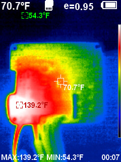
Here are some thermal pics taken during this:
First pic is of the entire board, seen from the component side with the raspberry connector at the bottom:
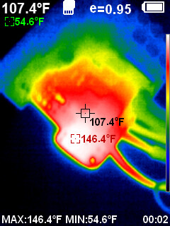
The second image shows a little more detail of the area on the bottom left:
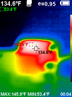
And the final image shows the back of the same area:
I have the following questions:
What does “fault” mean when reported by example.py? Is it a communication error or does it mean there is some sort of electrical problem?
It seems that the two chips on the bottom left of the board are getting very hot now. What is their function? Does it indicate they have failed or might there be an external short circuit (I’m hoping)?
If the board is destroyed, what is the most likely cause?
Why didn’t the current limiting circuit protect it?
What steps can I take to prevent this in the future? I’ve run the motor that the board wasn’t able to move directly of a battery and it worked.
Can you post specs for your motor as well as pictures of both sides of your board? Did you have any load attached to your motors when you were using them with the driver? Here are answers to your questions:
The fault reported in our example means that the nFLT pin on the board is being driven low indicating a problem detected by the motor driver. The detectable faults include short circuits on the outputs, under-voltage, and over-temperature. You can find more information about that in the product page description under the “Fault conditions” header.
The components around the bottom left corner of the board are related to the board’s reverse-voltage protection feature. Based on your pictures and the behavior you described, it seems likely that the board has been damaged.
Some common ways these boards can be damaged are from bad electrical connections and the motor drawing more current than the board can handle, leading to an over-temperature or over-current condition. When you post your motor specs and pictures I will let you know if any problems stand out.
The nominal current limiting threshold is set to about 40 A per channel by default. The board can handle transients that high, but it cannot continuously handle that much current. For future reference, you can adjust the current limit as described in the product page description under the “Current sensing and limiting” header.
Aside from basics like double-checking your electrical connections, the most important thing you can do to avoid these types of issue is to make sure that your motor, motor driver, and power supply are appropriate for each other. A conservative guideline is to use a motor driver which can continuously handle at least the stall current of your motor.
Thank you for your answers. I think the board is dead then and now I have some idea of what happened
The motors are geared motors from a high mileage wheelchair and there are separate brakes. I do not have specs on them, but I just took some measurements again. With the brake engaged, the current goes as high as 90 A (roughly; my current clamp is very imprecise).
However, I do not expect to have to operate it in anywhere near that range. The wheelchair had to have the power to move a potentially obese person uphill, while my robot does not have the payload, heavy steel chair or lead acid batteries. I can get the motors to turn under no load with a power supply limited to 1.9A and 1.5V, so the 24V14 seemed like it should be adequate.
But! This was no true for motor 2 when I tested it just now. As a matter of fact, I could not get it to turn until I connected it directly to my batteries. Once it had turned, I was able to run it with the low voltage and current mentioned above.
So it had seized - maybe the bearings in the old motor itself or the brake had seized and it required lots of torque to break it free. I imagine that when I made the foolish decision to disable the fault check in the example script this allowed the driver to continue to supply high current inadequate to break the motor free, but for a period long enough to destroy the board.
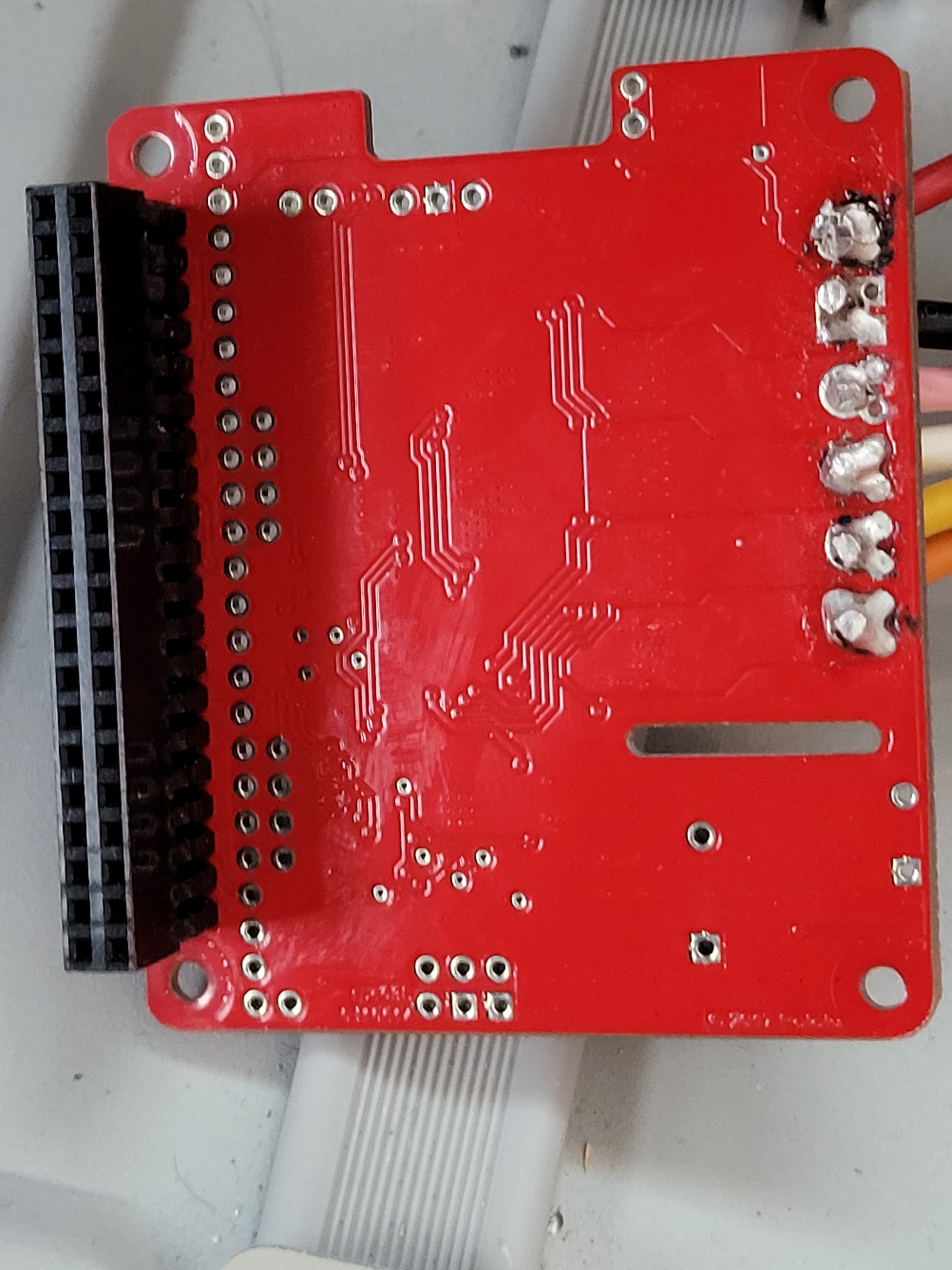
Below are photographs of the board. I’m not proud of the soldering. I normally stay at 630 degrees and I had trouble until I finally cranked the temperature up by another 100 degrees.
Given that the actual current needed is much lower than the stall current do you think the choice of 24v14 is reasonable if I monitor for fault and stop try to power the motors on fault, or would another board really be more appropriate?
I see now that I can add a resistor to lower the current limiting.
I think your explanation of what happened makes sense, and yes, in the future it will probably be better to identify the source of the fault before removing fault checks in your program. Despite the check being removed from the program, the internal circuitry that controls the nFLT pin should have disabled the driver for M2 to try to protect the driver. However, it is possible that the fault triggered too late to save the driver, or perhaps the driver damaged itself while trying to recover from the fault condition.
Regarding the soldering, it is normal to have to use more heat to solder to the large motor output pins since there is more copper leading to them, though it does look like the VIN pin probably overheated a bit. 730 F (~390 C) does not seem unreasonable, though, especially if you are using lead-free solder.
Given your 90A current measurement, I think the 24v14 is underpowered for your motor. Keep in mind that even with no load your motor will likely draw similarly high currents when starting abruptly or changing directions, and while the 24v14 can handle high transients, that is pushing its limits. Maybe it could be okay if you modify the current limit and implement some acceleration/deceleration limiting, but I think you would be better off with a more powerful driver. If you strictly want something in the form factor of a Raspberry Pi HAT, then our Pololu Dual G2 High-Power Motor Driver 24v18 would give you a little more safety margin. But I still generally expect that will be underpowered, so if the HAT form factor is not a rigid constraint, I would suggest looking at the RoboClaws and MCP Advanced Motor Controllers.
Thank you much for your help. I’ve ordered the 30A Roboclaw and I’ll start out with current limit set low and limit acceleration. Hopefully this will do the job!