I have used more than 50 of your boards in the past two years. All 50 were built with the same configuration and we have not had any real issues.
However, in the past month or so multiple boards have “randomly” stopped working. All I am getting is the solid red error light.
I am powering the boards through a 28V filtered power supply. Each board is controlling a 28V linear actuator.
I monitored the PWM signal going into the pic on the RX line. On the damaged boards it appears to be a tiny 600mV pulse.
On a good board I measured the signal as a 5.2V pulse. I tried adding a pull up resistor to see if this would help, and it increased the pulse to 900mV, but still no working board.
I am not sure if this was some sort of ESD shock on my input that has damaged the pics or another issue all together.
The input on the motor controller is a constant 5V. Whereas on a good board, its coming in as a 5V pulse.
Connecting the board to a PC using the Configuration Utility shows only one issue: invalid input.
I have tried returning the factory settings and modifying the settings for my current setup.
Do you have any insight or experience in this issue?
I will be playing around with this more and hopefully be able to give you more info as I get it. Thanks!
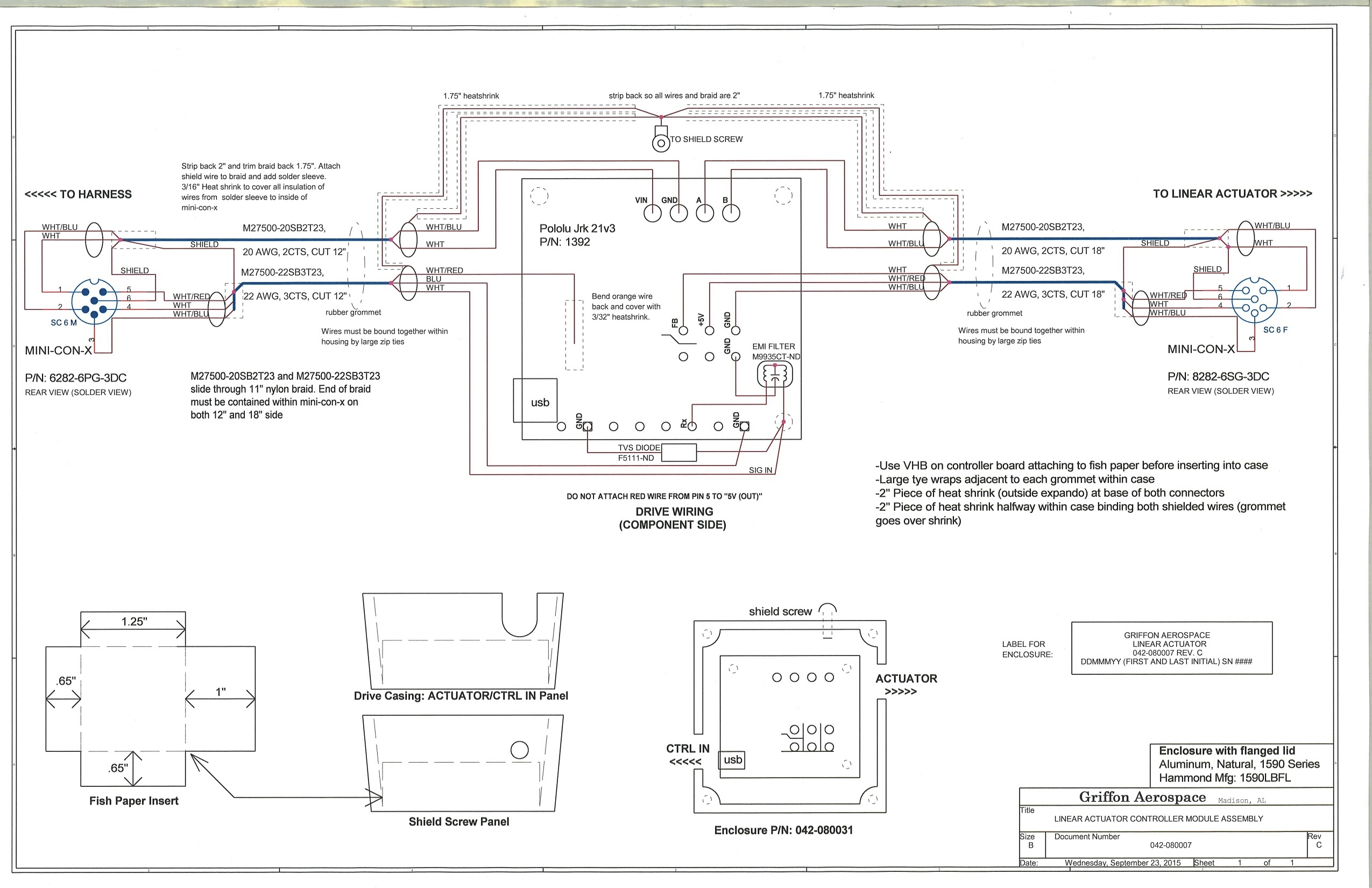
side note: On my Rx line I have an EMI filter as well as a TVS (the only real “modification” we make to the board):
digikey.com/product-search/e … M9935CT-ND
digikey.com/product-search/e … k=F5111-ND
I am not sure I understand your description of the voltage on the RX pin. First you mention that there appears to be a 600mV pulse, but later you say it is a constant 5V. Either way, it sounds like the input you are using is not a valid RC hobby signal with a pulse width between 0.4ms and 2.6ms. Do you have an oscilloscope you can use to look at the input signal, both before and after connecting it to the RX pin?
Have you tried swapping the nonworking board into one of your working setups? You might also want to save the settings file from one of your working boards and load it onto the nonworking one to make sure they have the same settings. You can do this using the “Save settings file…” and “Open settings file…” options within the “File” drop-down menu in the Jrk Configuration Utility.
By the way, 28V is right at the absolute maximum voltage for this board. You mentioned having a filtered input, but we would still recommend using a slightly lower voltage to leave room for noise/voltage spikes on the power line.
-Brandon
I apologize for the confusion.
The 600 mV pulse is coming into the pic on pin 12 (RB5).
The constant 5V is what is leaving the pic (via pins 6 and 7 (P1B and P1C)) and going to the motor controller (pins 1 and 2 (IN1 and IN2)).
I have a Hitec servo programmer/tester that provides correct signal to my working boards.
I did reload working code into the board with the same results, no movement and a solid red error light.
I replaced the pic on a damaged board with a pic from a working board and everything ran fine so I know something happened with the pic.
I am not sure if it was a spike in the 28V as you said, a spike on the IO line or something else all together.
It sounds like the RX line was damaged somehow; if this is the case, it might have been caused by the input signal. Were you connecting the same servo tester to the RX pin on the problematic board that you used on the working boards? Can you post some pictures of your setup that show all of your connections (including the TVS and EMI filter)?
-Brandon
In the instance when these boards were damaged they were connected to an autopilot.
I know the output signal of the autopilot is clean.
In my testing, I have used the same servo tester on all my boards.
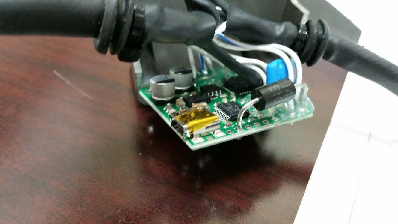
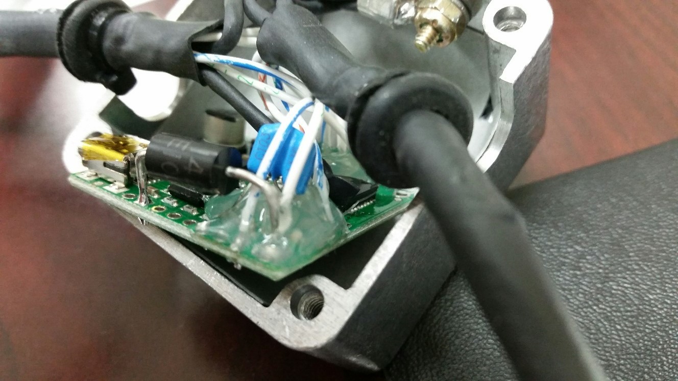
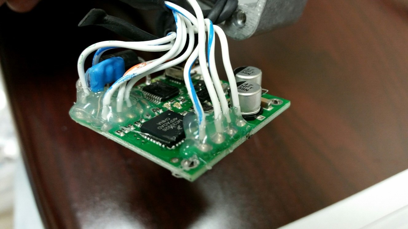
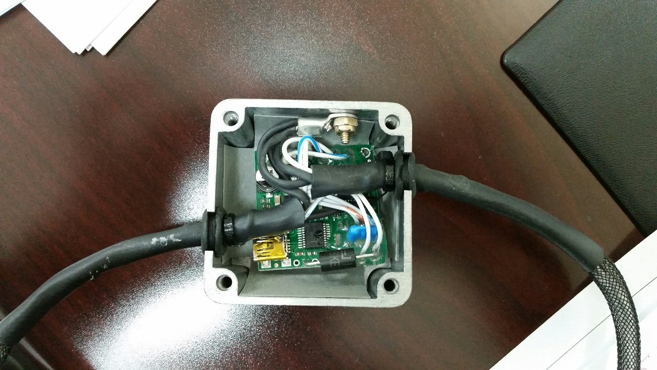
Attached is various pictures of my board design, with a schematic.
Thanks again for your help!
1 Like
Hello.
Are you really using the 8.55V version for the TVS? It seems high for a 5V line; how did you arrive at that value?
–David