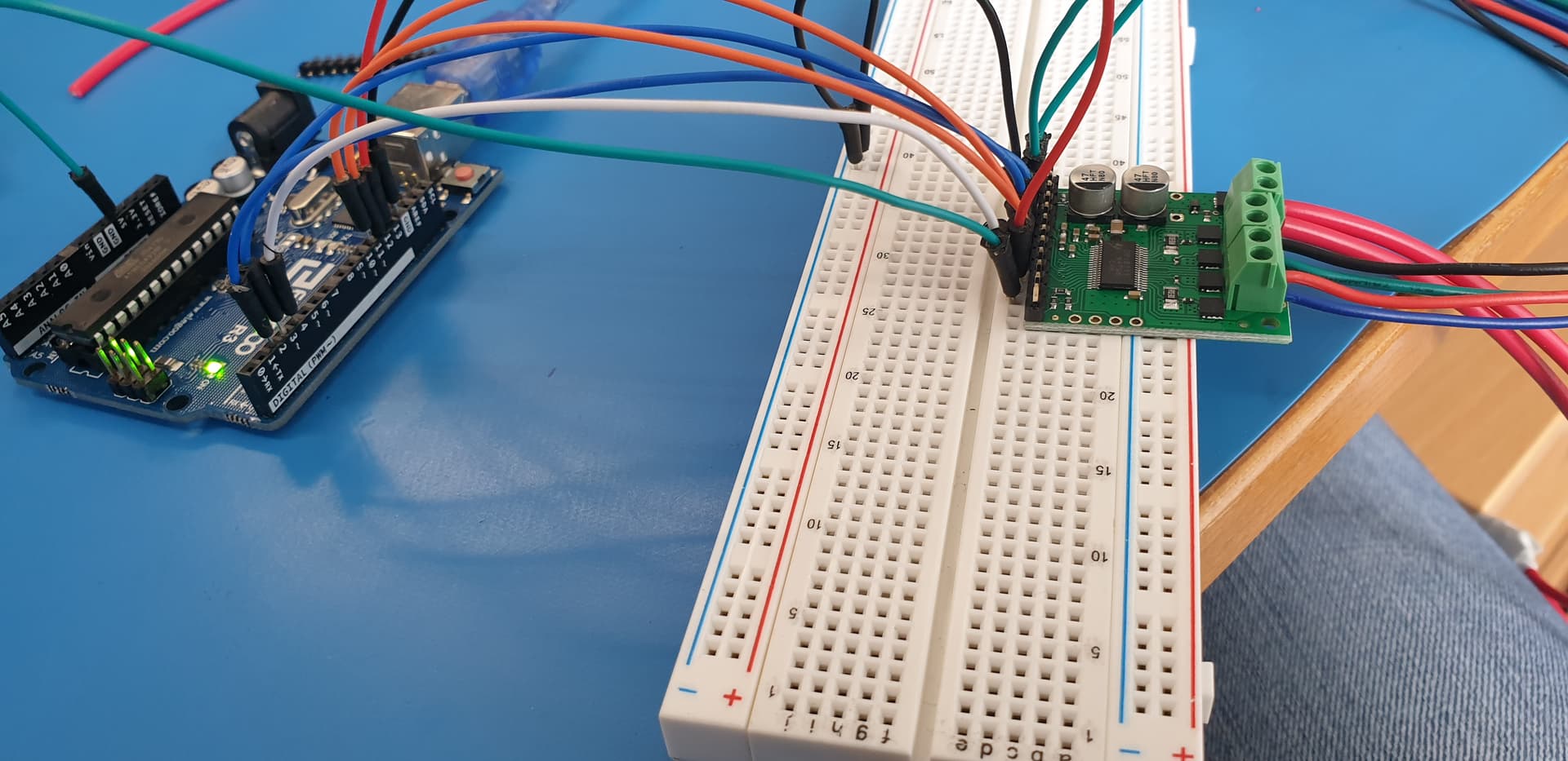
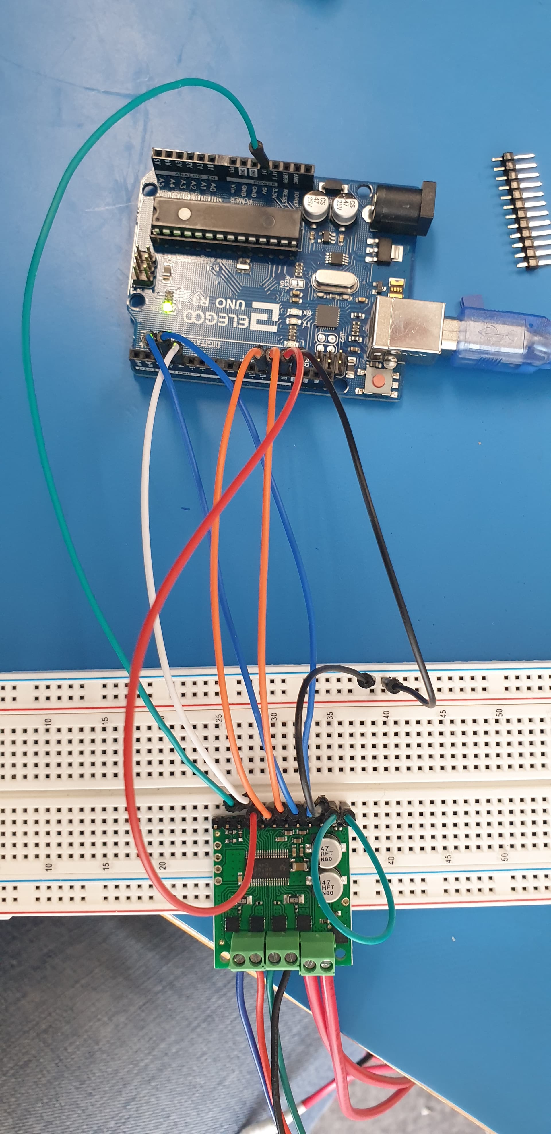
Hello, I’m trying to run the Driver with Elegoo Uno R3 (microcontroller ATMEGA 328P). the connection is as follow:
V5(out) → → IOREF
ARD GND → → GND
ARD D13 → → SCLK
ARD D12 → → SDATO
ARD D11 → → SDATI
ARD D4 → → SCS
ARD D3 → → STEP
ARD D2 → → DIR
ARD 5V →→ SLEEP
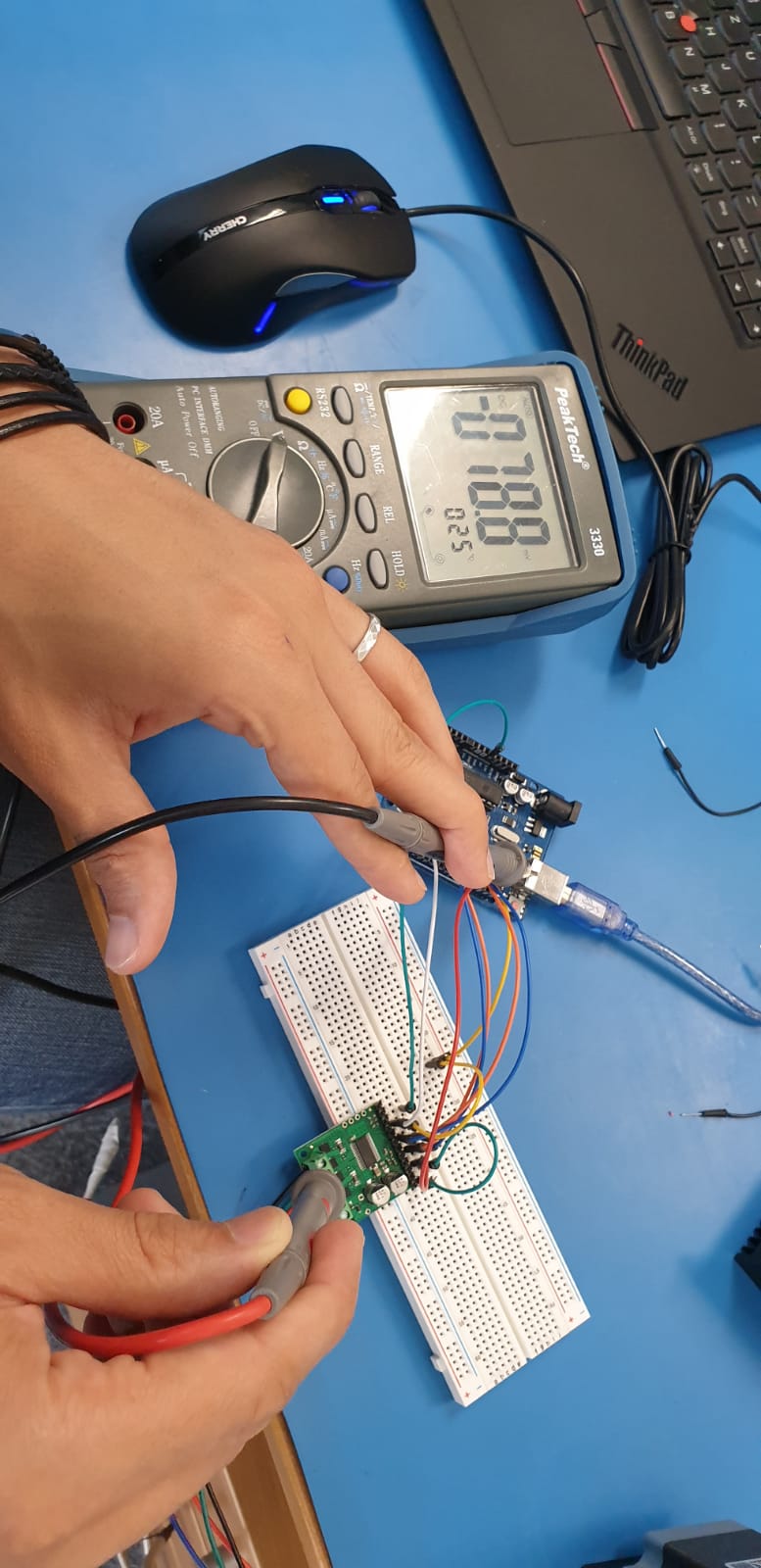
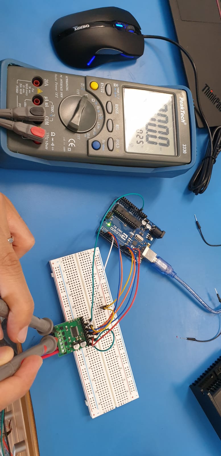
the power supply is 24 v. unfortunately nothing is running and when i measure the power supply i get 24 v but when i measure the voltage of both windings i get 0v.
if I try to measure the Voltage in the pins VM and GND I get 24 V
the Motor I am using is Nema23 (2.3 V / 4.2 A)
if I measure the winding’s voltage against the GND of the Arduino i get for all of them the same voltage (2.12 V) that’s why i am getting ( 0 V) if I measure the voltage of the windings on their pins.
but after a few minutes this common GND with the Arduino Board disappears and i get totally different values
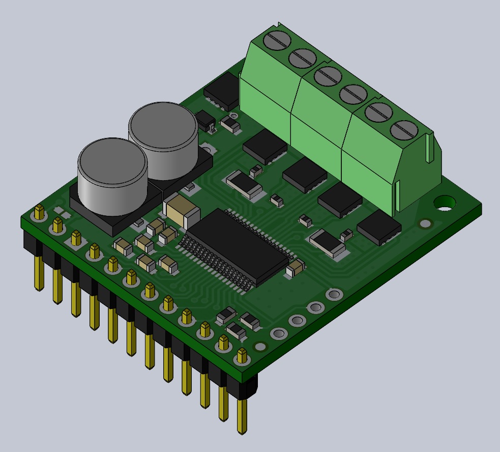
It looks like your headers are not soldered properly for use with a breadboard (or maybe not soldered at all), so it is probably not making good connections. If you want to connect your driver to a breadboard, you should solder the headers, with the black plastic part on the bottom side of the board and the short end of the header pocking through the board to be soldered. That way you will be able to plug the long side into the breadboard. Here is a quick rendering of that:
thank you for answering. I may did it wrong but the whole Time when I was measuring the Voltage on (nSleep) I got 5v (even with the bade soldering of the headers). or does this mistake affect the SPI -Pins more than the other pins?
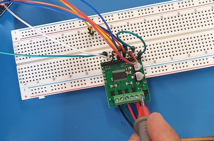
and sure you are right, i noticed my mistake about the Terminal Blocks and I fixed it, so I still have to try with the connection to the Breadboard
It is hard to predict how your system as a whole, the board, or any of the individual pins will behave when you do not have good connections. We do not recommend using electronics like these without good connections since that is necessary for them to work.
Also, just because you measure 5V when you probe a header pin, without having a good soldered connection, that does not necessarily reflect the voltage of the pad on the board itself. Additionally, poor connections could result in problematic (even potentially damaging) transients that a multimeter might not be able to detect.