Was hoping to be able to figure this one out myself however I’m officially out of ideas so I’m seeking ideas/suggestions. I can’t seem to get the Pololu Dual MC33926 Motor Driver Shield for Arduino https://www.pololu.com/product/2503 to work at all. First off some background, basically building a automated gate using an arduino Mega and some ebay linear motors. Why, cause I can and it was cheaper than buying premade given I had to replace the old gate anyway. Was a good project to tinker with anyway. The project uses the MC33926 motor driver to drive the motor for each half of the gate and I’ve managed to isolate it down to this component and/or code as the cause of the issue.
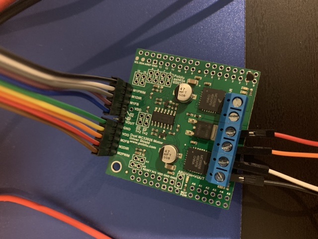
I’ve soldered all the required connections as per the general motor driver configuration rather than the arduino stackable headers configuration. This was done to allow flexibility on pinouts for the Mega in the final device. Since I’ve been having issues I’ve gone back to my bench Arduino Uno to get the code/driver working then will test on the Mega with the updated pins. All the pins are as per the default/as if you used the stackable headers configuration on the bench test. Note that none of the board jumpers have been connected as they aren’t needed given I’ve got flexibility with the jumper cables to choose whatever pin inputs I need. This includes the VDD/D2 jumper as well as ARDVIN=VOUT jumper as I supply the Arduino with power from elsewhere.
So what I have I done thus far to check it’s working: I’ve validated that the arduino is indeed outputting correctly using the default demo program by connecting some LED’s to the pins on the arduino which results in the following:
D2 (always high as per program)
M1DIR (high when going one direction, off for the other)
M1PWM (fades on/off as PWM is adjusted regardless of direction)
M2DIR (high when going one direction, off for the other)
M2PWM (fades on/off as PWM is adjusted regardless of direction)
As such all of the above appear to be working as expected so the issue doesn’t appear to be with the code. When I connect all the pins (except VOUT as the arduino is powered via the DC plug) to the motor driver I tested the analogue outputs which seem to be more or less right. They aren’t perfectly zero all the times as they fluctuate a little however generally they’re OK and only reading up to a max of about 63mA with nothing connected to the M1 and M2 outputs. SF was tested by connecting from the motor driver straight to an LED rather than to the arduino. SF was always high but a bit dim when compared to the brightness of the LED’s tested above. Not sure why. It didn’t flag any faults on the arduino when running the program with everything connected despite nothing happening so I don’t think this is an issue.
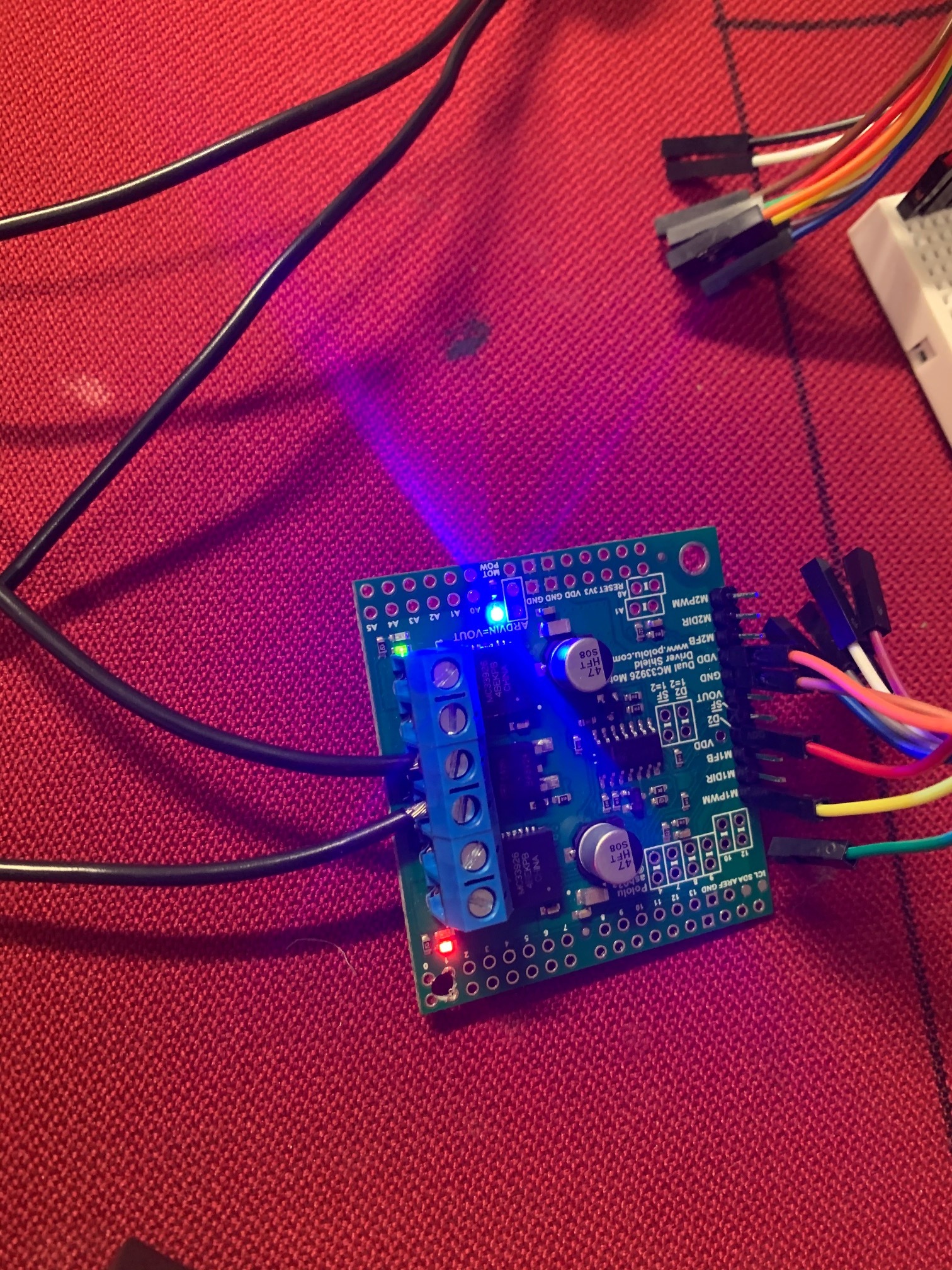
When power is applied to the motor driver high current terminals the blue LED for MOT POW is on. Throughout all testing I’ve never seen the two LED’s near the motor driver outputs on. I tested a 12v LED and some 12v motors and these worked when connected directly to 12V supply however when connected to one of the motor outputs, nothing happens. Voltage at these outputs when testing remains at 0V. The high current supply is powered off the same supply that powers the DC plug for the arduino and as such shares a common ground.
I’ve also checked each jumper wire/soldered connection has good contact with the board. This was done with a multimeter between the arduino end of the jumper wire and the stackable header holes on the motor driver. All the Arduino side connections are fine. I haven’t checked the high current side to that extent as I’m not really sure where I can grab another point of these from. Measuring between the screw in the screw terminals and the non soldered part of each hole (given you have three hole options for the high current side) seems fine and shows good connection.
Any ideas, suggestions to try or anything would be appreciated as I’m really stuck on this one and feel as though I’ve run it to ground with no result or missed something really simple.
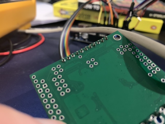
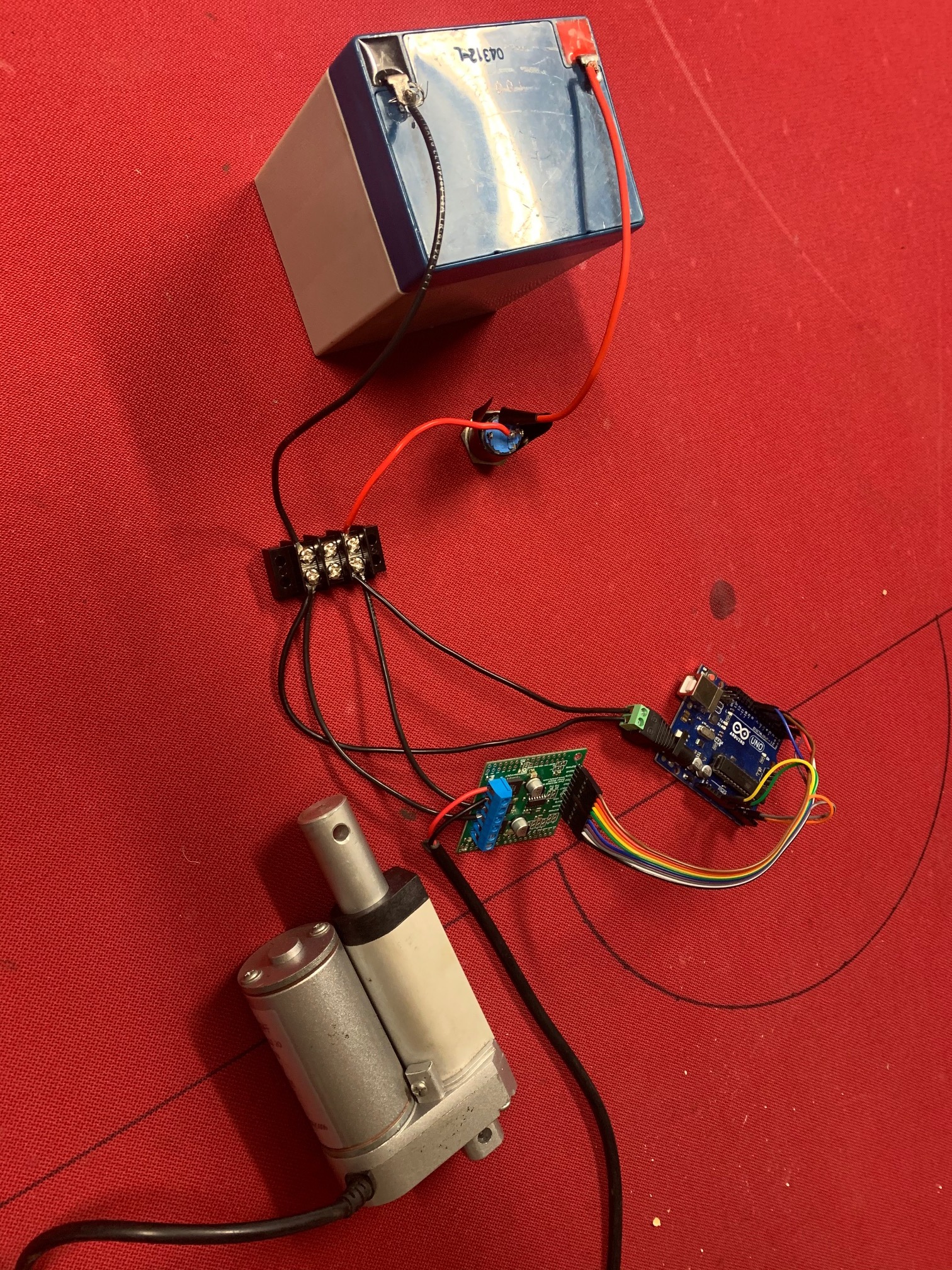
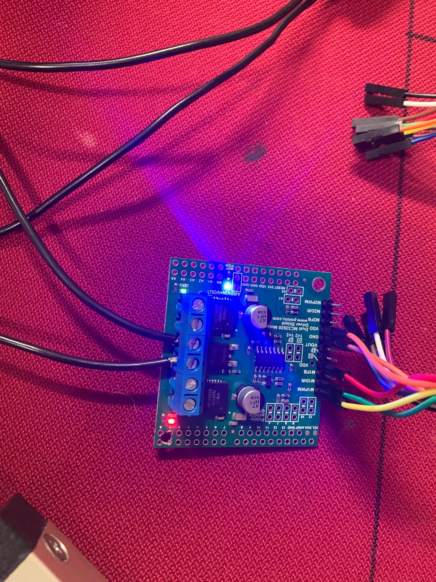
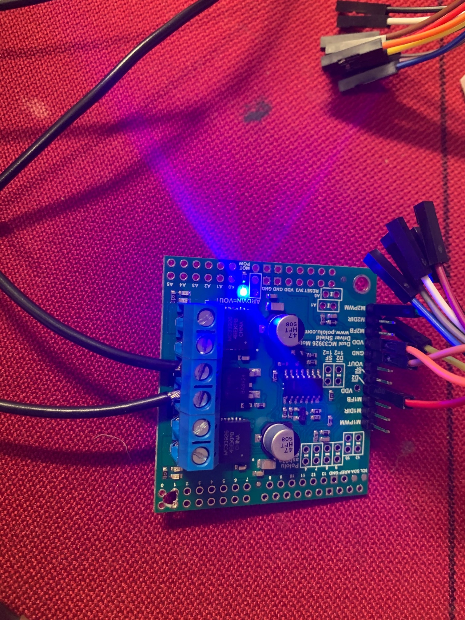
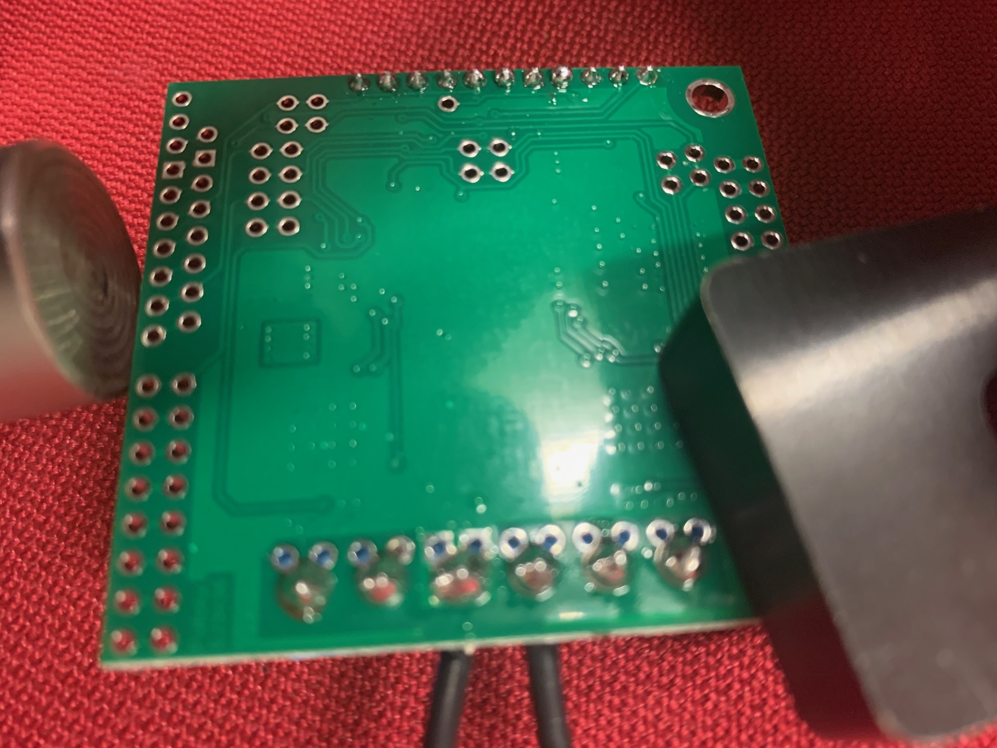
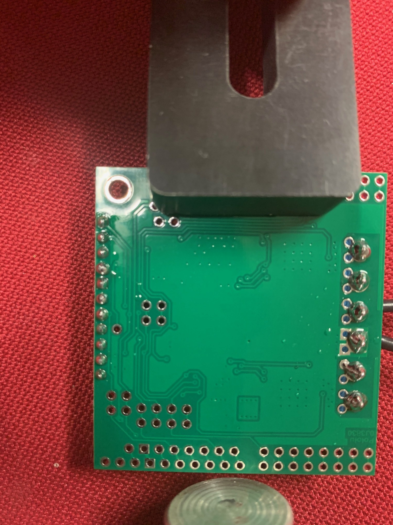
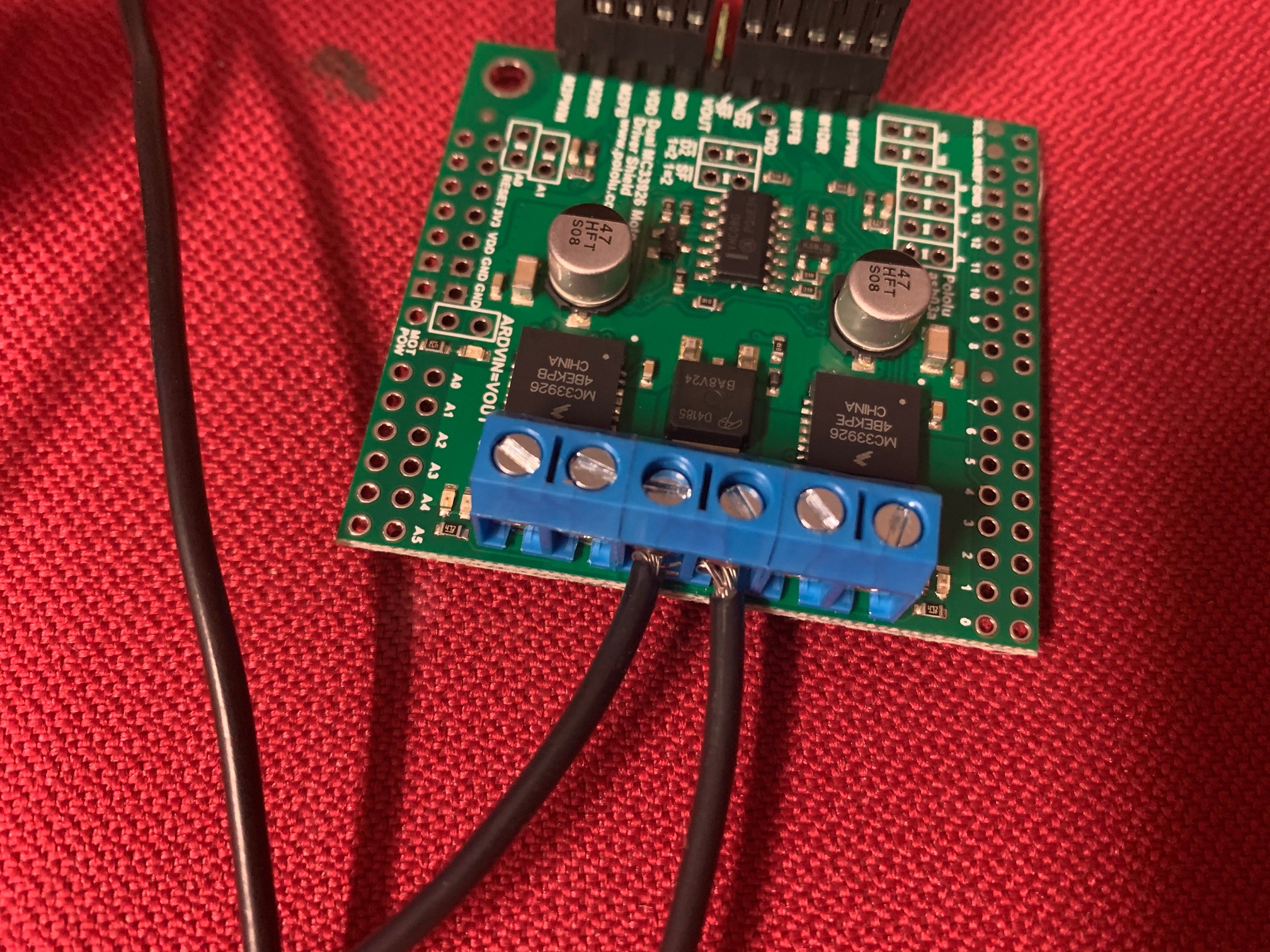
Photos below for reference. I did drill a small hole in the opposite corner to the factory one for more secure mounting after confirming that these connections did not appear to be used for anything so I wasn’t damaging anything/shorting anything. Note the light gauge wires on the high current side are only for testing a low power 12v LED strip to test if it was working.
Could you provide a diagram or list of the connections you’ve made between your driver and Arduino? Are you using the example program included with our DualMC33926MotorShield library? What are you using to power the driver?
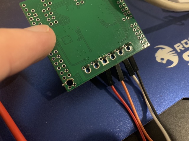
Some of your solder connections look like they could use more solder, although if you have already checked for continuity across them, they might be okay. If you want to try touching them up anyway, you might find the Adafruit Guide To Excellent Soldering helpful.
Additionally, the terminal blocks are intended to be installed in the larger through-holes, although they should work fine in the smaller holes and it is probably not worth the trouble of desoldering and moving them. However, you might find this video on installing terminal blocks to be a useful reference in the future.
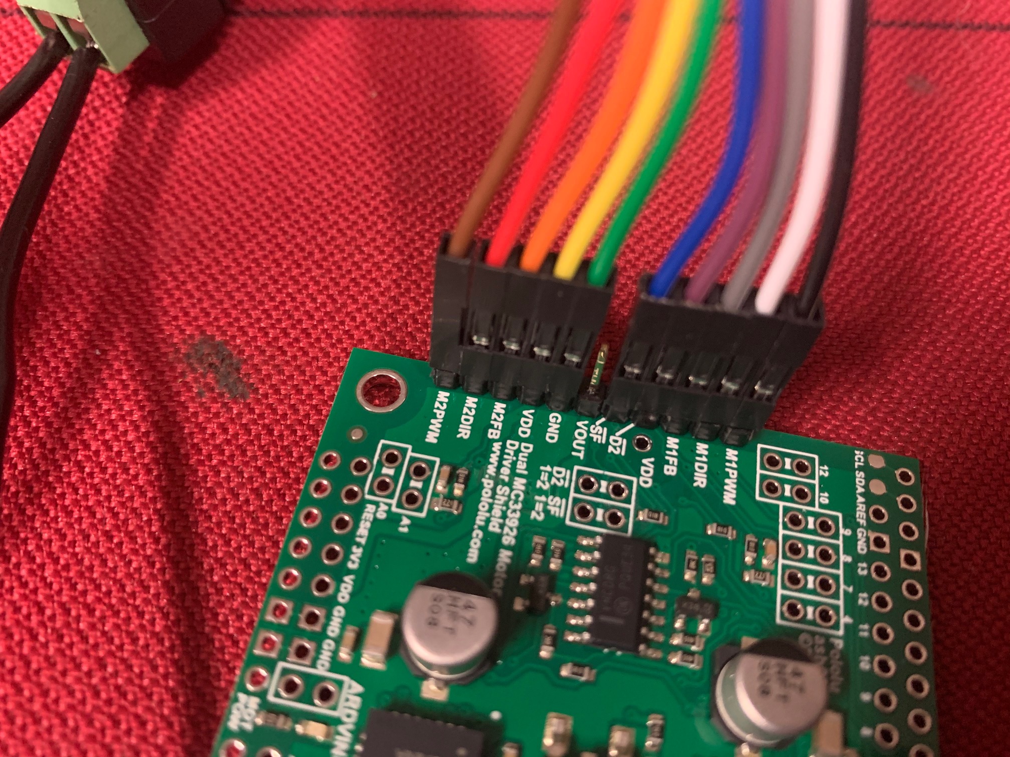
Connections are as per the Arduino Stacker header arrangement. i.e.
M1PWM - D9
M1DIR - D7
M1FB - A0
D2 - D4
SF - D12
VOUT - not connected
GND - Arduino GND
VDD - Arduino 5V
M2FB - A1
M2DIR - D8
M2PWM - D10
Power is provided by a 12v battery to the arduino DC plug as well as to the high current inputs on the terminal blocks. Voltage on battery remains reasonably constant around 12v even when each of the motor outputs is supposedly working. When connecting to a computer via USB 12v power and gnd is still supplied from the battery to both the arduino and motor driver.
I am using the example program included with that exact library with no changes whatsoever.
I’ll try and resolder them all again in an hour or so and see if this makes a difference. Not confident it will change anything given the multimeter check but will give it a go. Will post back regardless with results when this is done.
Re-soldering complete and it only JUST works…sometimes. Basically M1 in it’s first direction seems like it’s trying to work and the red LED comes on but not for long enough or it will be more of a flicker than solid on. Motor will occasionally move during this time. After this it doesn’t do anything until you reset the power on both. Seems like it’s flagging a fault. It won’t travel reverse at all like it’s supposed to in the program. Tried swapping M1 and M2 PWM and DIR wires to see if I could get M2 output to work and it doesn’t seem to do anything at all. No LED, no motor movement, nothing. Doesn’t seem to fault though as it still seems to progress through the code to try and move M1 then fault.
Only change to setup was to connect it to the actual motor i’m going to use to test so I can validate forward and reverse and change the high current power in wires to something with a bit more substance so they won’t fry in half a second trying to drive the motor.
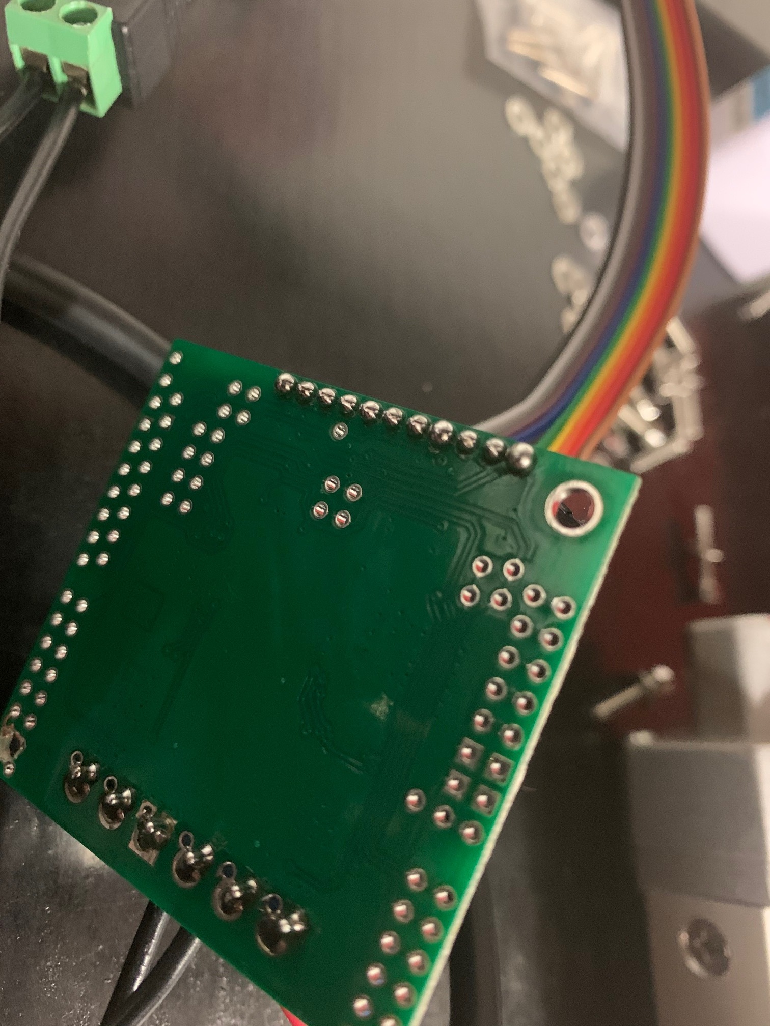
Re-tested all the connections and they all have good connection between the stacker header pin holes, through to the general purpose arrange pins, through the jumper leads to the arduino solder on the back side of the Uno board.
Thanks for the additional information. Your list of connections looks fine and your solder joints look better in your latest pictures. If the motor is only sometimes working, it suggests there might still be an intermittent connection somewhere. It’s possible that there is something wrong with the board, but we do test every unit before it ships, so it should have been working at some point. Additionally, since each motor channel is driven by a separate IC, it seems unlikely that both would be bad in the same way.
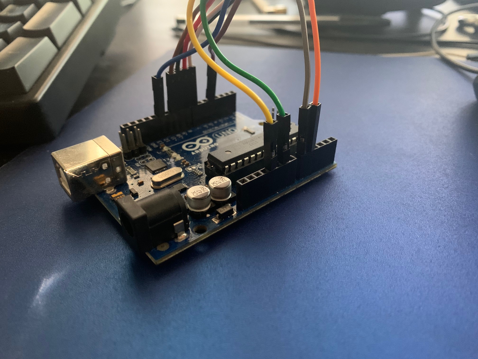
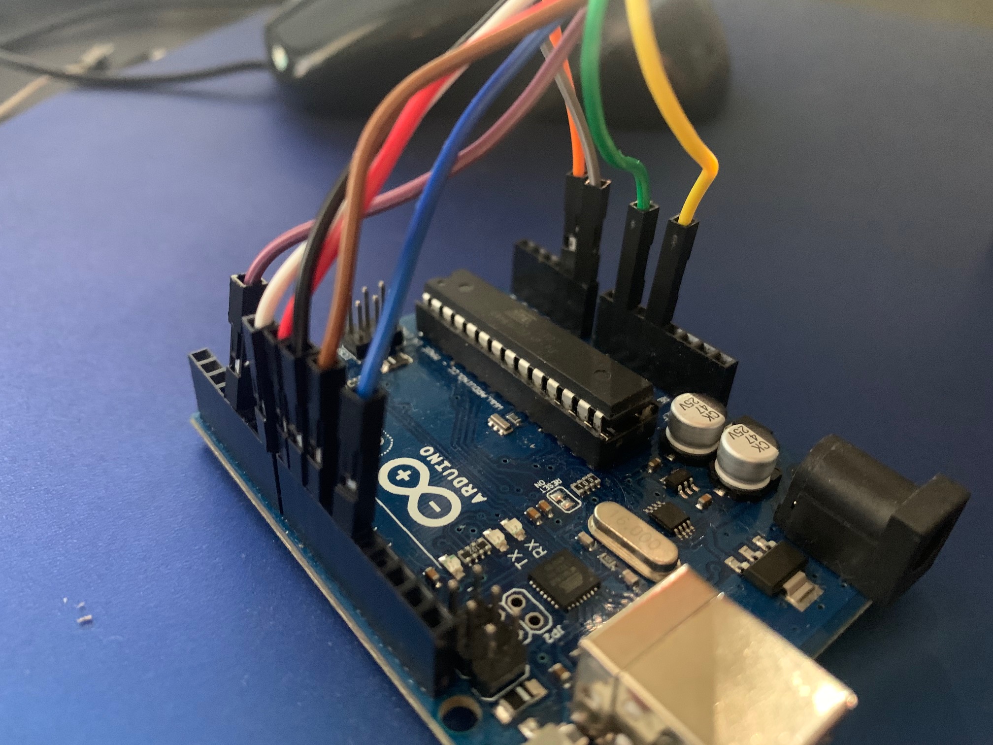
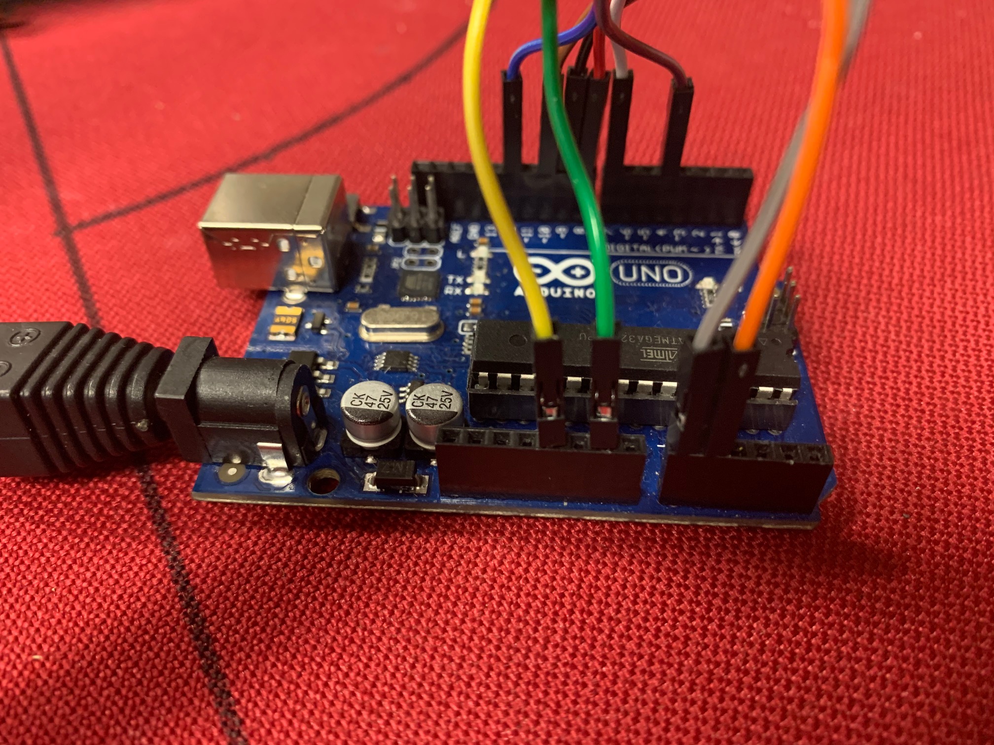
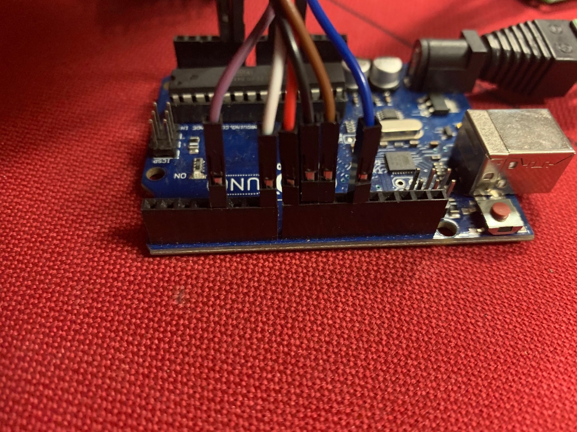
If you post some more pictures showing the connections in your setup, including on the Arduino side, I can see if there are any obvious problems with your wiring. Do you have an oscilloscope that you can use to monitor voltages and signals at various points in your system?
Hi Kevin,
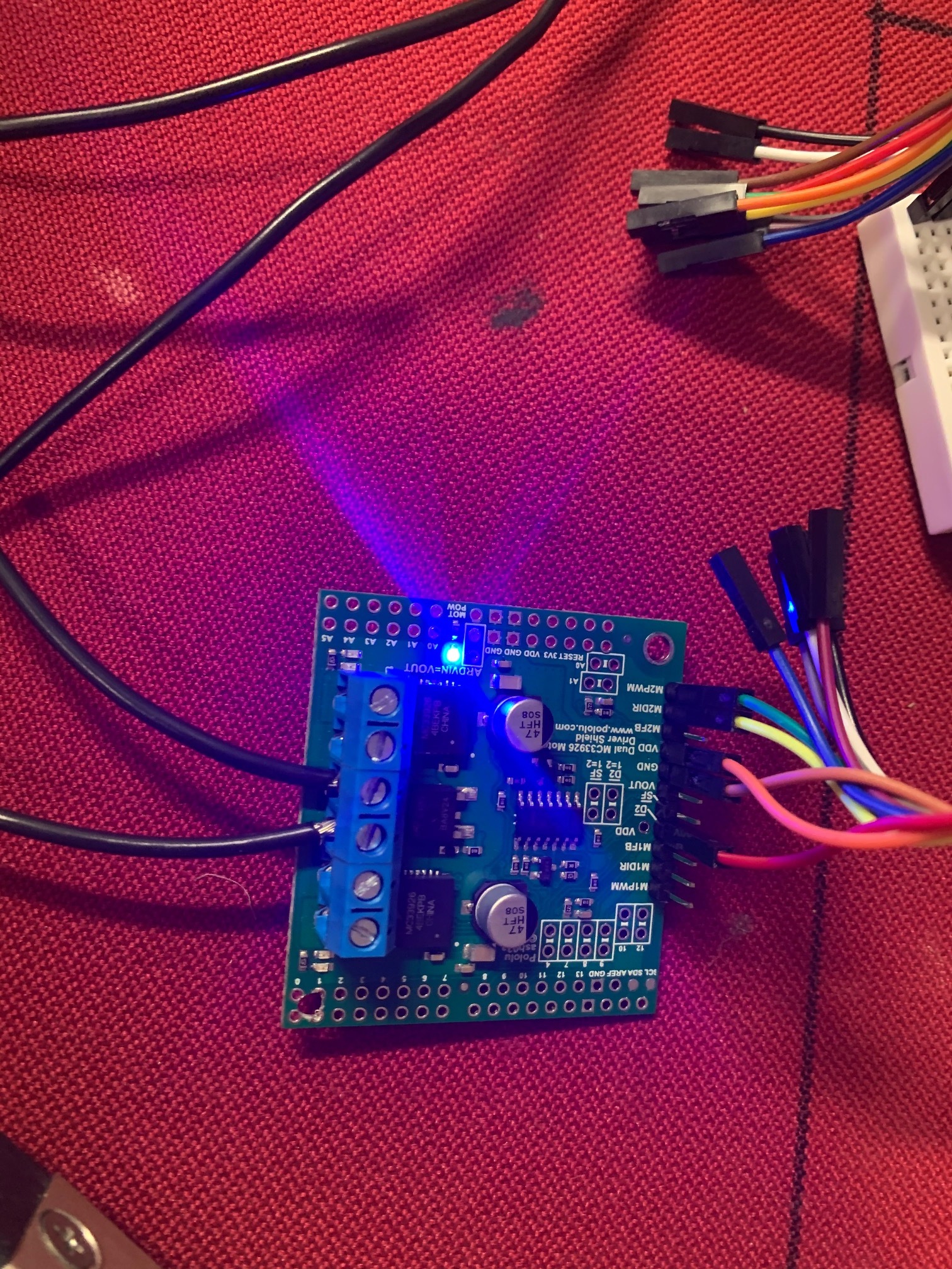
Pictures as attached. The little bus bar and switch was just to make power easier when testing and turns power on/off to both the arduino and motor controller high current side.
Unfortunately no oscilloscope. Only have a digital and an analogue multimeter.
I don’t see any problems with your connections. Could you check what the Arduino is printing in the Serial Monitor while the example program is running (both with and without a motor connected)?
It might also help us figure out what is going on if you try testing the driver by itself without the Arduino. To do this, connect 5V to the driver’s VDD and D2 pins, along with a common ground connection between the driver and your 5V source. Then, if you connect 5V to M1PWM, you should see one of the M1 indicator LEDs light up. If you additionally connect 5V to M1DIR, the M1 LED for the other direction should light up. You should also be able to repeat this with M2DIR and M2PWM and see the corresponding M2 LEDs light up.
Still seems like something weird is happening like an intermittent connection somewhere. Will try plugging in serial monitor first thing in the morning (your time) unless you’ve got something else to suggest before then.
Hi Kevin,
Plugged the laptop in with all the power connected to try and see what the serial monitor was doing. Program seems to be rolling through everything just fine. No faults are reported until I turn off the power to the motor driver/12v to the arduino at which point the motor driver board turns off. No lights are turning on except for the blue power LED though throughout the program (not even a flicker).
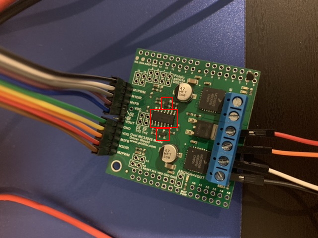
Managed to get a hold of a thermal camera and it appears as though three components are getting ridiculously hot (touch and it feels like your finger is burning) only after a few seconds of power on. They’re highlighted below and appear to be the logic IC and two adjacent diodes (I’m not an electronics expert by any means when it comes to this lower level of detail but I think that’s what those three components are).
The arduino’s 5v regulator module is also getting ridiculously hot as well not sure if that’s related or a just a function of feeding the Arduino 12VDC. Not sure if either of these hot components are related/a symptom of something failing/failed or just part of the design.
Thanks, the thermal camera observations are useful. With that information along with the results from your direct wiring tests, it seems pretty clear that the logic gate IC has been damaged; that would be consistent with the DIR and PWM inputs not working as expected. Just to be safe, I would recommend that you avoid using it with your Arduino anymore (if the chip is internally shorted, there is a chance it could damage the Arduino’s pins, although I think that isn’t too likely).
Did this driver board ever work properly for you, or did you have trouble getting it to work ever since you first tried it? Could you please email your order information to us at support@pololu.com and reference this thread?
Hi Kevin,
I’ve had trouble right from the start getting the board to work. All I ever managed to get it to do was turn the blue power light on and that was it.
Email sent about 12 hours ago. I purchased from the Australian supplier Core Electronics so not sure how that works with yourselves.
Hi Kevin,
New board, new solder, same setup. See attached pictures for your review before I apply power. If you see any issues let me know. Hopefully the soldering is a bit better this time to start with.
Tyler
Hi Kevin,
That’s fixed it. LED’s on each side now change intensity depending on your PWM. The LED’s on the same side are also activating one after the other i.e. green on, then off, red on then off, then it goes to motor 2 side LED’s and does the same rather than previously where the LED’s were doing all kinds of weird things.
Thanks for your support.