
Hi,
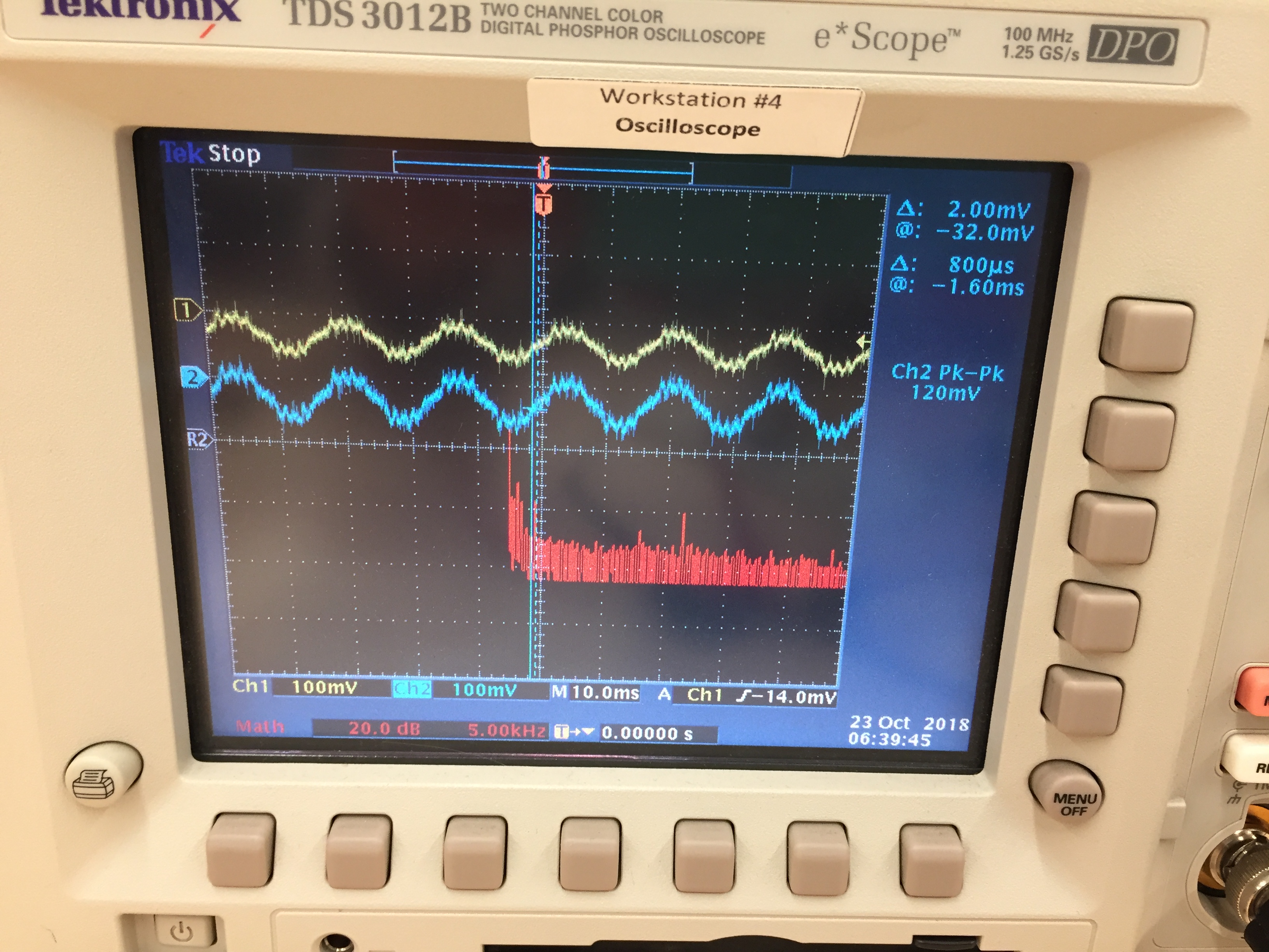
I purchased the DRV8834 Breakout Motor Driver to use with the Pololu 3.8V, 670mA stepper motor (product #1205). I completed the current limiting and actually set it slightly lower (VREF = 0.3V) than what is required. I wired up everything according to the minimal wiring diagram shown on the DRV8834 product page, and used the code provided for the circuit limiting video tutorial. I am using an Arduino Uno and I am using an external power supply where I can control the voltage and current output. I can hear the motor turning on and the shaft resists being turned, so the power is being provided to the motor. However, the shaft is not turning. I hooked up the A1/A2 and B1/B2 outputs to an oscilloscope, and the waveforms don’t look correct. The A1/A2 and B1/B2 outputs are in phase, and I think they should be out of phase to allow the motor to actually turn. Additionally, the timing of the outputs are incorrect. According to the code provided by Pololu, the waveform should have a period of 500ms but on the oscilloscope, I am not obtaining that. Does anybody have an suggestions for what to do?
Hello.
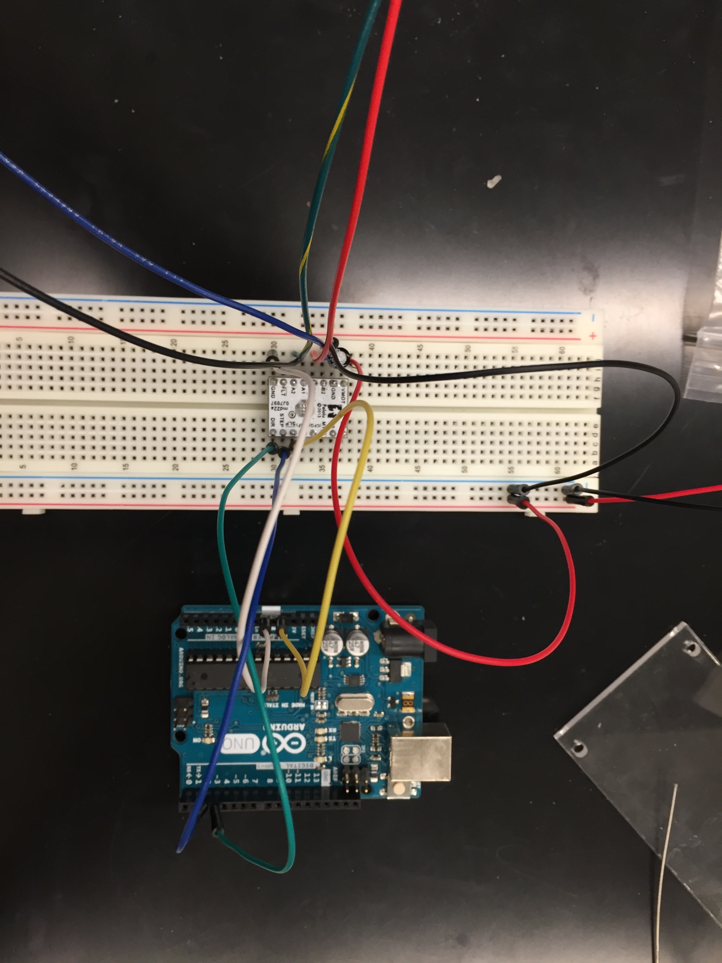
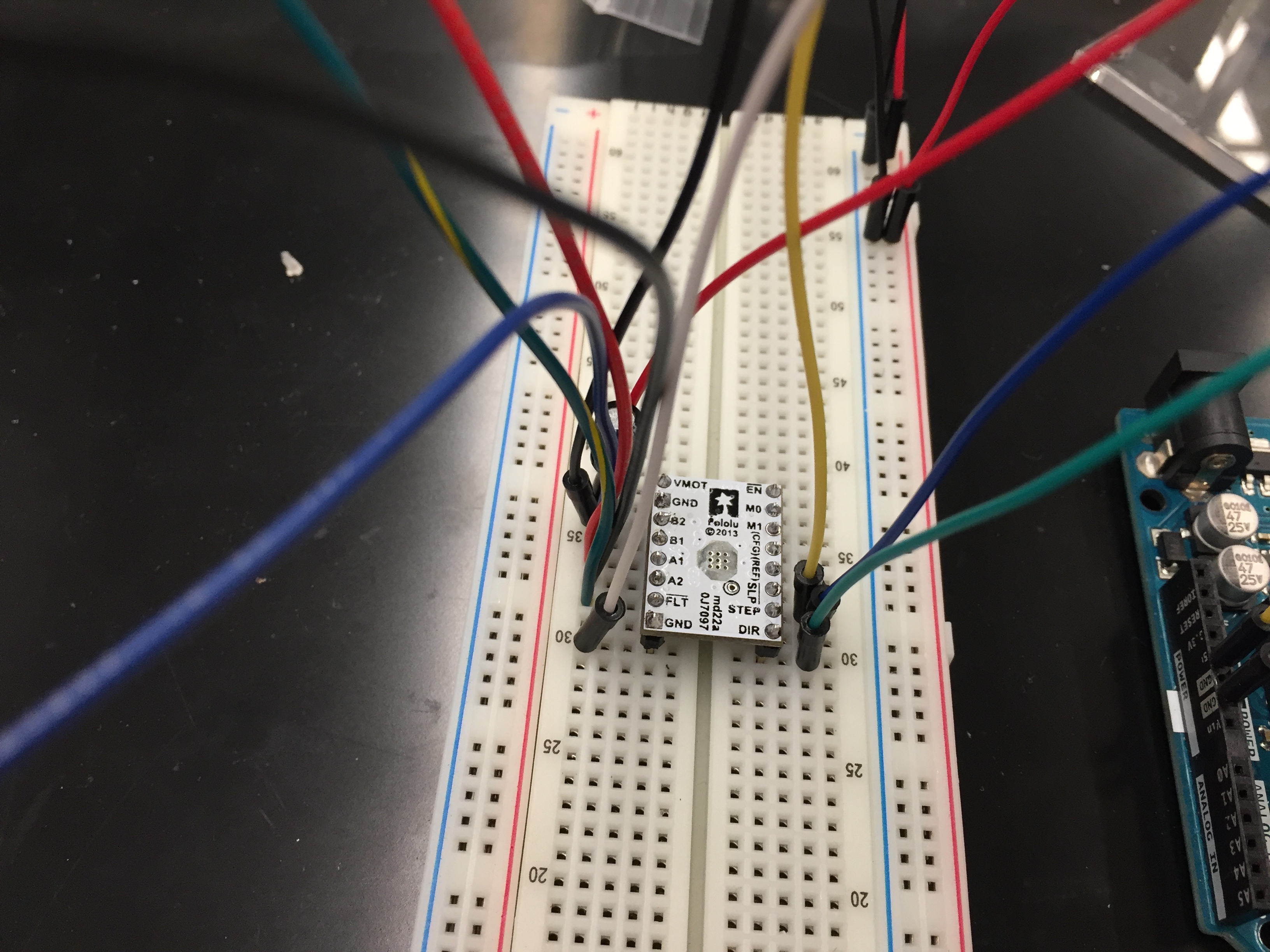
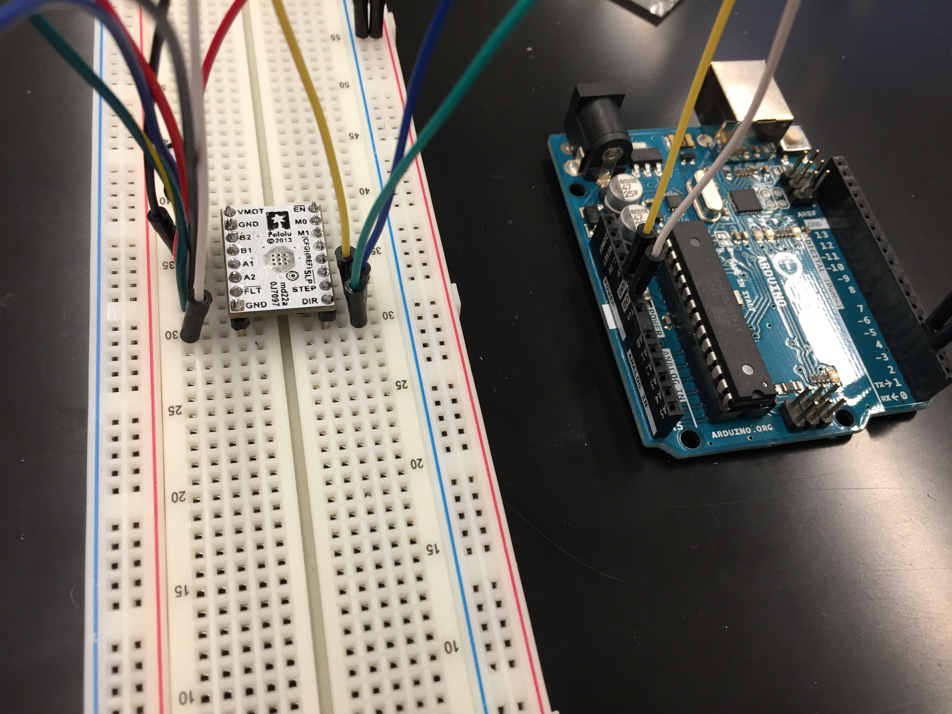
What voltage are you supplying to VMOT? Can you post pictures that show your connections to the driver including any soldered connections you made? Do you have a load on your motor?
The driver is meant to control current and in many cases, it may switch the voltage at a much higher frequency than the step rate to do so, which might be what you are seeing with the oscilloscope.
-Nathan
Hi Nathan,
I am supplying 3.8V to VMOT. I am also limiting the current from the power supply to 670mA as backup. I do not have a load on the motor. I have attached pictures to this reply.
Hi Nathan,
I changed my setup so that M0 is held LOW instead of FLOATING to put the motor into full step mode. I wired up everything else up just like before and now I can see the motor is turning. However, the problem is that it will move 1 step, then move back to its original position; thus, it is making no net progress. It is functionally stationary. Why is this happening? I am still using the example code given by Pololu from the current limiting tutorial video except I have changed the delay to be 2 seconds instead of 500ms.
Thank you for posting those pictures. Are you connecting the grounds of your probes to two of the coil outputs (A1, A2, B1, or B2) at the same time? The IC connects those outputs directly to VMOT and to GND through a low value resistor at different points in normal operation. Connecting two of those outputs together (through the ground bus of the oscilloscope) would create a near short circuit between VMOT and GND and could damage the driver. That could also damage the oscilloscope and you generally should not connect the ground clips of an oscilloscope to anything but ground.
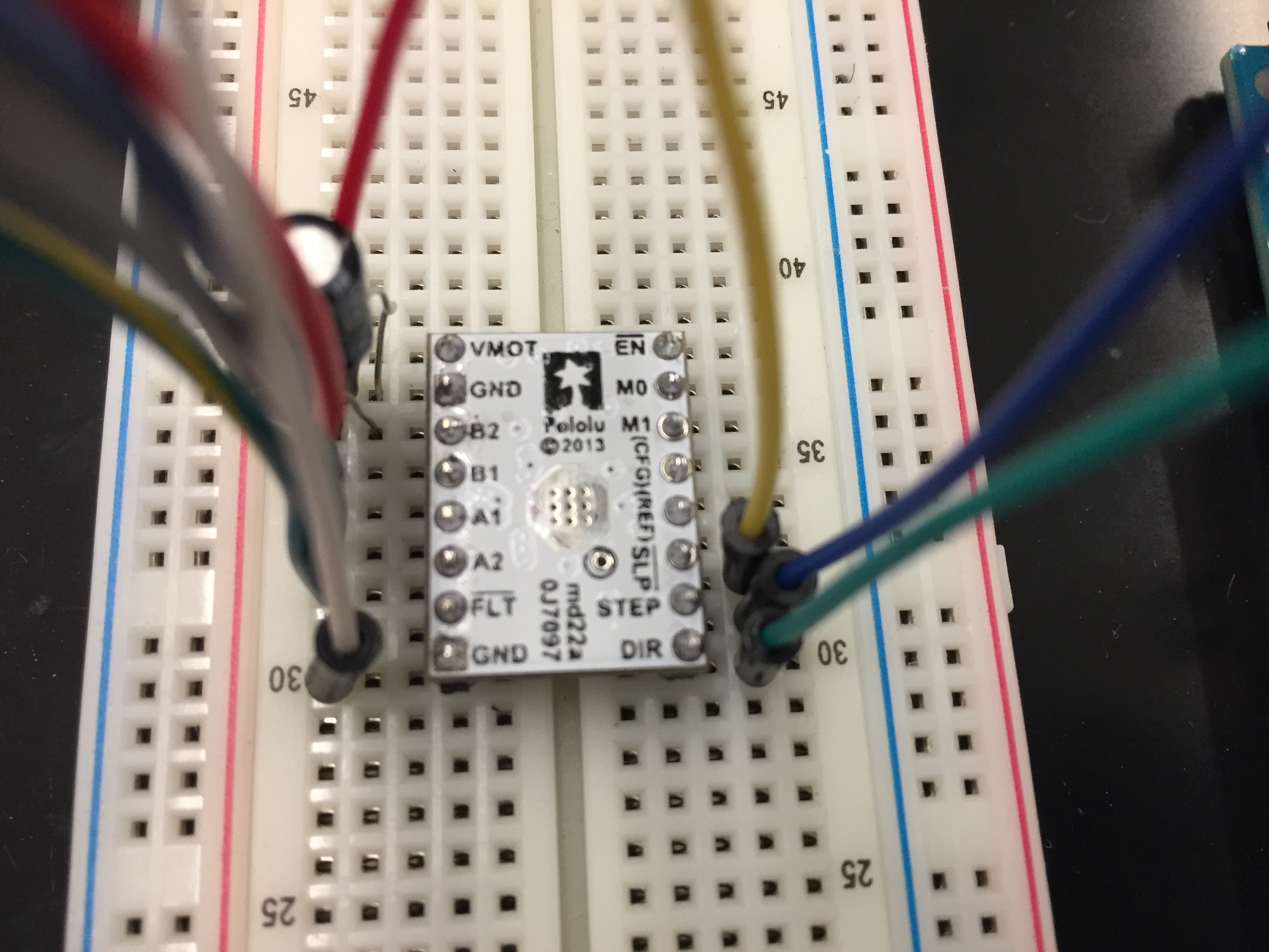
Some of your soldered connections (especially the M0 and M1 pins) do not appear to be wetting the pad of the PCB, which could create unreliable connections. Could you check your joints against those shown in the “Common Soldering Problems” section of the Adafruit Guide To Excellent Soldering, retouch any that do not match the ideal soldering joint shown there and then post pictures of them so we can see if they look OK?
Could you use your oscilloscope to measure that the voltage of the step pin at the PCB is changing from 0 to 5V (relative to the ground of your system) as expected? Also, you should check the voltage of the SLEEP pin at the PCB to make sure it is at 5V.
-Nathan
Hi Nathan,
-
It seems that you are suggesting my connections to the oscilloscope might have damaged the driver. I would like to note that the driver was exhibiting the same behavior as I mentioned above before I tried any sort of analysis, so the situation remains unchanged.
-
I checked my soldered connections with a multimeter and all connections are functional.
-
I used an oscilloscope to measure the voltage of the STEP and SLEEP pins. Both are functioning correctly, with the STEP voltage changing from GND to 5V every 1 second, and the SLEEP pin is constantly held HIGH at 5V.
Phillip
If I was not clear, connecting two of the driver outputs directly together through something like the ground bus of the oscilloscope could definitely damage the driver (as well as the oscilloscope itself) in some situations. It was not clear to me whether you damaged your driver that way (if it is damaged) or even if that is how you had the oscilloscope connected (though the fact that the voltages your oscilloscope shows are negative suggests that you are connecting the ground clips to something other than ground).
I just noticed the current limit setting you mentioned for your power supply. There are two coils on the stepper that the driver controls and the 3.8V 670mA rating is for each of the coils, so it does not seem like your driver would be able to source enough power from the supply with your settings and might be browning out. Also, one of the key features of a current limiting stepper driver like the DRV8834 is the ability to use a supply voltage that is higher than the rated coil voltage. Could you try setting a 5V, 1.2A limit for your supply to see if that works with your setup? Alternatively, you could try setting a lower current limit like 300 mA for your motor coils with the same power supply settings. In general using low settings like that make damage less likely in the case where something is connected in a way that creates a short.
-Nathan
Hi Nathan,
Sorry for the late response. I have tried both of your suggestions but it is still not working. What should I do in this situation?
Phillip
Did you retouch the solder joint for the SLP pin connecting to the PCB like I mentioned before? If so, can you post a picture of the retouched joint here so we can inspect it?
-Nathan