Hey. I generally would just buy another one because I made a stupid assumption, but as the onboard chip has under/over current/voltage/temperature protection on almost everything, it seems a little unlikely that it would blow. There’s a bit of a back story as to what happened, and the current status of the board at the end (skip there if you want). Hopefully it isn’t too confusing, but there’s a lot of stuff going on.
To give a brief electrical layout:
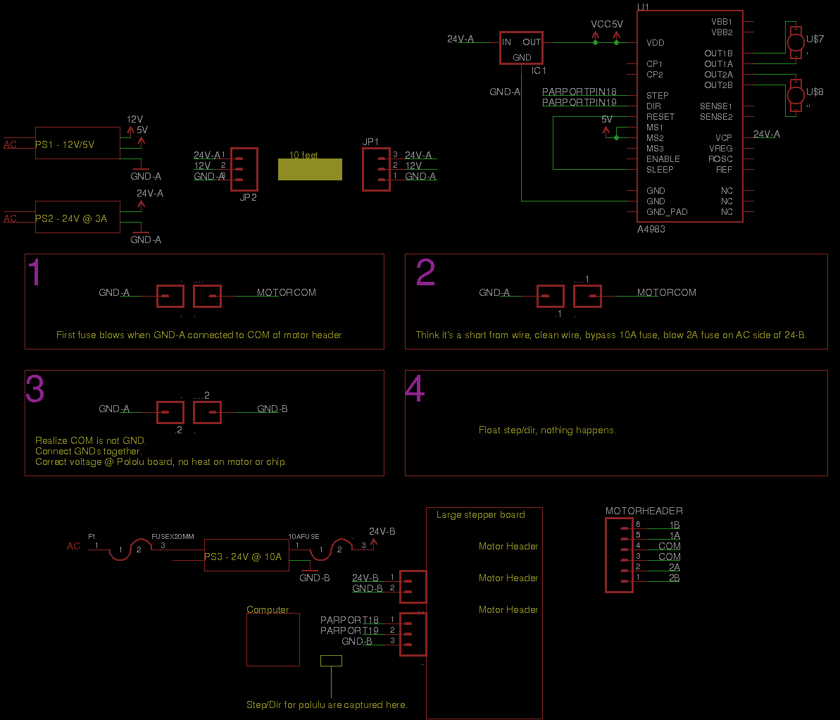
I have 1x 12V [relay controls, Arduino] /5V supply, 1x 3A 24V supply [pololu stepper driver and 40W power resistor connected to this], 1x 10A 24V transformer (connected to bridge rectifier) [Large stepper motor driver connected to this].
I got this stepper motor driver about ten days ago. I got it all hooked up on my desk, it was working great. I’m making a 3D printer, and hobbling together all the parts I can. I have a different 3 axis motor driver board for my other steppers, but it can’t drive bipolar motors so I needed to get the Pololu part. I was driving at about an amp with 5Vdd supplied.
It was on my desk, working great driving from my Arduino (for the step/dir pins). I was powering it with a 24V supply for the motor, and using an 7805 5V regulator to drive the logic. The grounds were connected, and it worked!
The trouble started when I attempted to interface this board to my computer / other stepper board. My other stepper board is connected through the parallell port on my computer, it’s running linuxcnc, and I was able to get everything to work with my main stepper board off. This stepper board has 4 axes of control, but only three are in use. I soldered two step/dir wires for my fourth motor onto the parallel port connector for my other stepper driver.
This worked well when the other stepper board was off, but because axes 1/2 and 3/4 share logic on the board, when I turned the other stepper board on the voltage dropped on the signals sent to the polulu board, and it would no longer work reliably. I figured two things needed to be done: cut the traces for the step/dir pins going to the pololu board, and connect the grounds between my fourth axis and the rest of the axes. Now my assumption -> this other driver is a 5/6/8 wire stepper motor driver. There are a couple labels on the board -> A, a, COM, COM, b, B. I figured COM would be the same as system ground. I didn’t ohm it out (stupidly) until whatever damage was done. I did not turn the board on at this time, I cut the traces going to the logic chips on board the stepper board. After I cut the traces, I turned the power on.
The 10A fuse on the stepper board blew.
Interesting… I figured there was a short from something when I was cutting the wires. I found a wire that looked to be shorting something. Cool, found it. No more fuses… This system is double protected with fusing, there’s a 10A on the DC side, and a 2A on the AC size (taking 120Vac and outputting 24Vdc).
I shorted the 10A fuse holder on the DC side, leaving me 2A on the AC side. Okay, now we’re playing with fire.
I turned the large stepper board on. Good to go, fans on, everything normal. I can drive around on all axes. I turn the 12V supply on (powers Arduino, relays, etc.). Good to go! One last supply, the other 24V supply (the +24V lines are NOT connected). I plug it in… whooooommmmmmmmm. Everything dies. Okay, something bad happened. I ohm out the ground that I assumed was ground, it was not. I connected it to the ‘proper’ ground, got some more fuses, turned everything on, and action!
I felt the 7805, it was blisteringly hot. It’s taking 24V and dropping down to 5V, that would get pretty hot, but let’s swap it (I don’t even remember if I check the output). I powered down, figured there might be a short, connected VDD up to the 12V supply’s 5V output. No motor output when driving step/dir from computer. Check voltage of step/dir, 3.83V on dir, .1V on step (I don’t have a very good multimeter and also don’t have an oscope). I desolder step/dir (if they floated before, it would make the motor go crazy), nothing. No craziness like before.
Current status: Feel the chip, no heat. No heat on the motor. VMOT is ~23 Vdc (with a capacitor connected across VMOT and GND), VDD is ~4.83V, with a cap across VDD and GND. The reason for the voltage drop is the length of wire (~10 feet). If step and dir float, there is no output. 0V on enable. .56V on Vsense. No voltage on motors, and they have ~8 ohms of resistance (didn’t destroy the motors). It seems like the system is on, but there’s just no life inside.
My prognosis: when I connected the ground to the COM of the stepper driver, I was not connecting to ground. For some reason, a huge insurge of current came about because of this, and blew my 10A fuse (this part is weird, I think it may have been a two for one problem or something with a short, and a faulty ground). When I shorted the fuse holder, the 120V fuse tripped only when I plugged in the 24V power supply. Because the ‘ground’ of the larger stepper board was higher than the ‘ground’ of my 24V supply, all the current wanted to go to the large stepper board’s ground. This ‘ground offset’ made 0V look like negative X volts on the step/dir pins of the pololu board, destroying it instantly. But that wouldn’t kill the chip, at least from the data sheet, as it has no minimum voltage for logic 0, and no maximum voltage for logic 1.
I can answer any questions, and do any more tests to see if it’s truly destroyed. I’d like to revive this thing so I don’t have to wait a week for my new one to come.