I’m in the process of designing a circuit to control four 18v25 CS motor drivers from a Teensy 3.2. I’ve almost got everything setup and working perfectly, but I’m having difficulty reading the fault codes.
I’m using a Microchip MCP23017 I/O extender running at 5v (because there aren’t enough pins on the teensy) to read the fault flags for the 4 controllers. Each of these lines is pulled up to 5v with a 4.7k resistor. I tried this without pull-up resistors and the ‘high’ signals from the motor controller where around 1v.
The strange behaviour I’m seeing is that both the FF1 & FF2 lines are identical. I’m able to test the under-voltage and short-circuit faults easily but both fault conditions result in FF1 & FF2 going high. If the voltage was low and I increase it back to 14v then both flags go low and the driver starts working again. I the short circuit fault was triggered, then a reset gets the board going again and sets both flags to zero.
Also strangely if I pull the reset pin low to disable the motor controller both the fault flags go high, in a case where there is not fault! It appears that both FF lines are high when the driver is disabled/off and low when it is running
I’ve tested the impedance between the two fault flag pins with the driver taken out of the circuit and I get 94k ohms, is this the expected value?
Does anyone know what’s going on here? What is the recommended circuit to read these fault lines?
The High-Power Motor Driver 18v25 CS already has 47k pull-up resistors to 5V(out) on its fault lines, so you should not need extra pull-ups or other circuitry. Could you measure the voltage of the 5V(out) pins on your drivers with a separate multimeter? Be careful not to short it to the neighboring V+ pin since that could instantly destroy the driver.
Are you seeing this exact same behavior with all 4 drivers? If you disconnect the fault pins on one driver from everything and measure them during an under voltage fault, do they still both go high? Could you post pictures that show all of your connections?
I tested the value of the 5V(out) pin and it is consistently at 4.65 volts, dropping off when the supply voltage goes below 6 volts. This actually explains why the current sensor was centred around 2.35 volts instead of 2.5. I’m now powering this from a separate 5v source.
I’ve just tested the voltage of the two fault lines without them connected to anything and the results are very strange. During normal operation and when the driver is disabled by pulling RESET low both lines are at 0v, so far so good. Shorting out the motor coil pins disables the driver and both fault lines go to 1.5v. After resetting the driver I trigger the under voltage fault by lowering the supply voltage to drop below 4.3v this results in a voltage of 3.75 on both fault lines. In fact the voltage on both fault lines is exactly 500mv below the supply voltage while it is lowered in the fault condition.
I’ve only got two of the driver boards at the moment, and I’ve just tested the second one with the same results described above.
At what voltage is the under-voltage fault meant to be triggered, I couldn’t find this information anywhere. I’m assuming it’s not meant to trigger below 5v because then how would it generate a 5v logic high?
Does any of this behaviour make sense? Is there any firmware that could be at fault on these boards?
Thanks.
Ps, my breadboard is currently a mass of level shifters and I/O extenders, a picture wouldn’t be easiest thing to get any more information from.
The table in the “Fault Conditions” section of the driver’s product page, lists that the under-voltage fault should cause both fault lines to go high. As I mentioned in my last post, The fault pins are pulled up on the board to the 5V(out) node, so if that falls below 5V, I would expect the fault lines to only get pulled up to that line’s current voltage. So it sounds like the under-voltage condition is triggering the fault pins as it should.
To troubleshoot the short-circuit fault more I suggest taking one of the drivers completely out of the current “mass of level shifters and I/O extenders” and connecting it to just a power source. Then measure the fault lines with a meter while shorting the outputs. If you still get the same behavior, please post pictures of that setup that show your connections including the short and soldering.
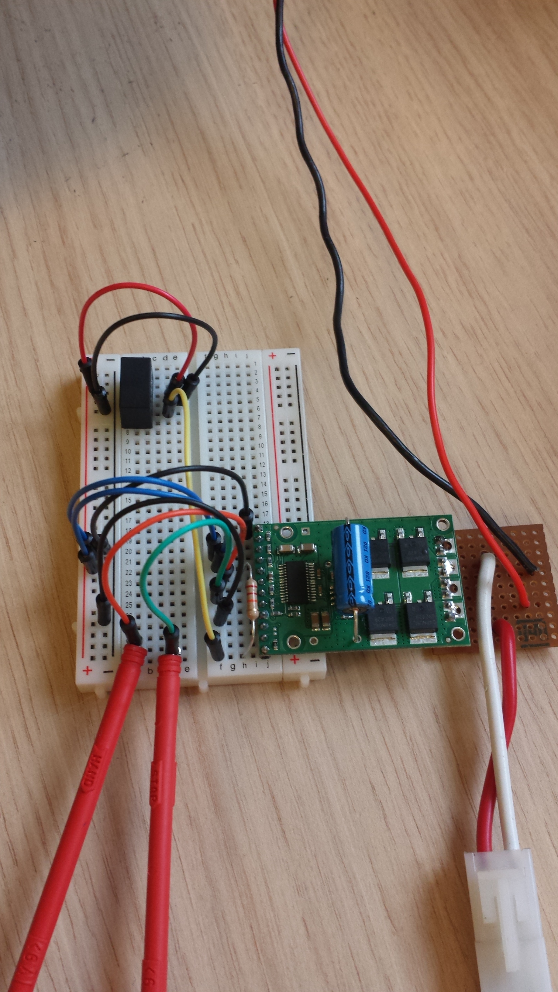
Hi Claire, I’ve simplified the circuit as you recommended to demonstrate the problem I’m having. I’ve added two pictures of the circuit and made a video so you can see the effect changing the supply voltage has on the levels of the two fault lines.
Let me describe the circuit quickly: I’m running a regulator off the V+ pin to provide a 5V source, which is driving the Dir and PWMH high. There is a 20k resistor connected between V+ and RESET to enable the controller. The two ground pins are connected, not sure if this is necessary or not. The two fault lines are connected to probes.
In the video here you can see the setup with both fault lines being metered. As the supply voltage is lowered the undercurrent fault only triggers around 4.2 volts. Because it is being triggered so low the fault lines only ever go up to 3.5 volts, never reaching a 5V logic high level. What level is the under voltage fault meant to trigger at, and is there a way of setting this level?
Strangely with this same setup, a motor short circuit wasn’t triggering a fault and latching, just maxing out the bench supply and generating a lot of heat! It was latching fine on the previous breadboard.
Claire will be out for a few days, so she asked me to continue helping you.
The under-voltage fault on the High Power Motor Drivers is not triggered at a well-defined voltage, and the threshold cannot be changed, so I expect it to be normal for the supply voltage to drop somewhat below 5.5 V before the fault is triggered. I think you are seeing the expected behavior when you intentionally try to trigger an under-voltage fault.
Meanwhile, given that you are using a benchtop supply that will try to limit the current itself, it’s possible that you won’t be able to trigger a short circuit fault reliably without the power supply’s current limit kicking in. If the power supply was dropping its voltage before the driver could detect a short circuit, it might have triggered an under-voltage fault instead, which might explain the behavior you were seeing earlier. If you have access to an oscilloscope, try probing the driver’s V+ pin to check if this is happening.
To try to trigger the short circuit fault more reliably, you might want to ensure that your connection between the motor outputs has as low of a resistance as possible (e.g. with a thick wire with a short length) and try making the connection both before and after turning on the power supply.
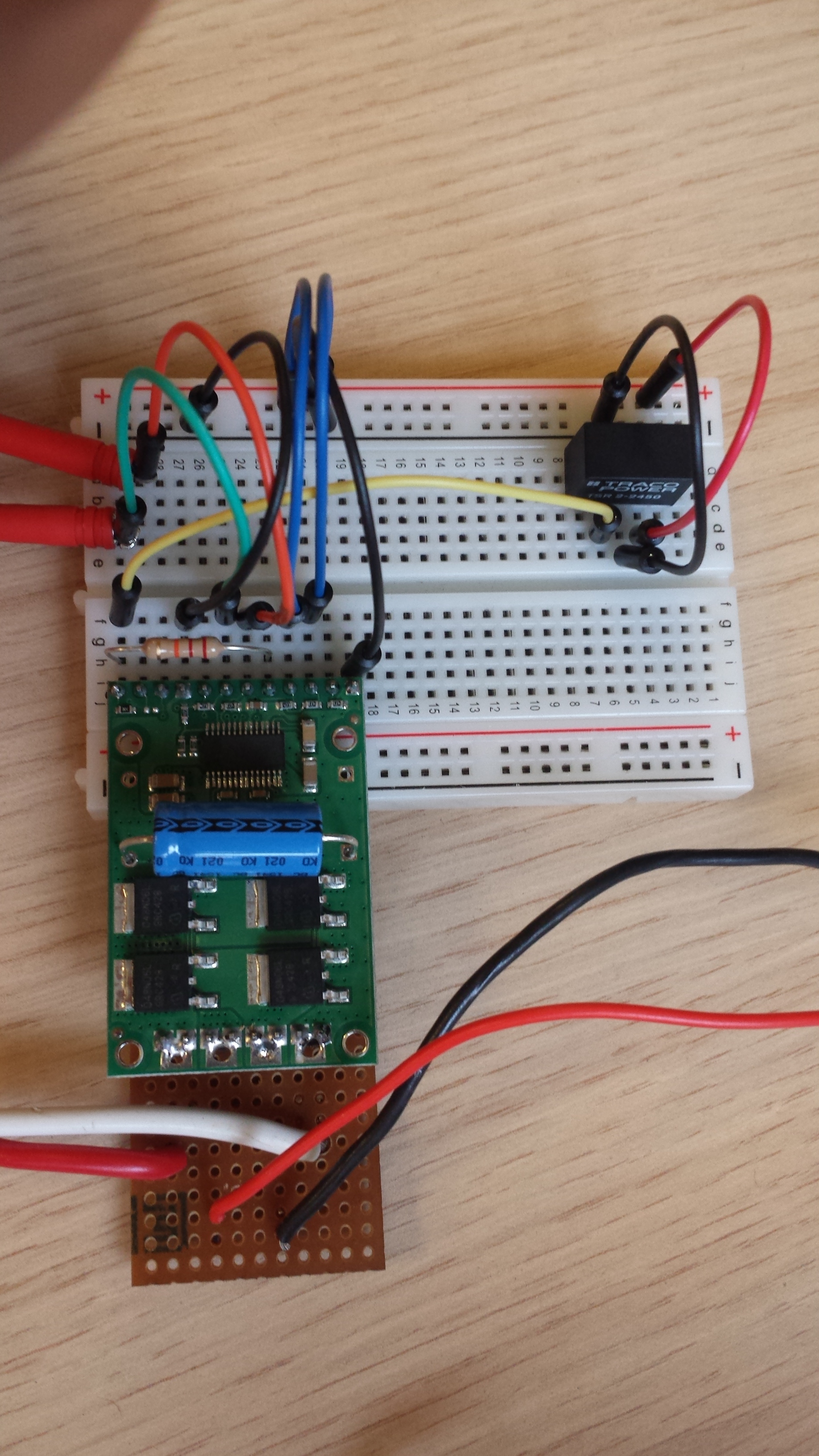
Thanks for the reply, I’ve just uploaded a new video showing the short circuit fault being triggered using my full breadboard. This fault can be triggered fine with this setup using the same power supply.
In this video the same two yellow meters are showing the two fault lines, and the green meter is showing the voltage between the GND and V+ pins of the motor controller. As you can see the short circuit fault successfully latches and disables the motor but the two fault lines both go to 1.5 volts, even though the V+ voltage stays around 14 volts. Measuring the resistance between the two fault lines reads 94k ohms, so there isn’t a short between them.
Do you know of any explanation for this or do I just have some dodgy boards? Everything else on them works perfectly but the fault flag lines don’t behave at all as described in the documentation. The under voltage fault is triggered at such a low voltage that a 5V logic high is never produced.
Do you have a reference circuit design that has been used to show these fault flags working?
From your video, it still seems possible to me that you are actually triggering an under-voltage fault, especially since it looks like the constant current indicator LED is lighting up on your power supply whenever you connect the short. Because both the power supply’s current limiting and the driver’s fault detection work on such short timescales (on the order of microseconds), a multimeter will not give you any indication of the brief drop in voltage that could be happening if the power supply clamps its output and the driver immediately stops. This is why I recommend using an oscilloscope to monitor the supply voltage to see whether that’s the case.
If you do not already have the current limit on your supply set to the maximum, you could also try gradually increasing it to see if that might allow the driver to detect a short before the supply’s current limit kicks in.
Unfortunately, there is no way to trigger the fault pins other than actually creating a fault condition, and the only faults that should result in different voltages on the two FF pins are short-circuit and over-temperature (which would be difficult and risky to induce).
I don’t understand why you think this could be the under voltage fault, because this fault is latching and the under voltage fault doesn’t latch! I have to cycle the RESET pin using the micro controller to active the driver after shorting the pins, this isn’t necessary after the under voltage fault.
Since the short circuit fault is the only one which latches, I’m sure that this is the fault that it is being triggered. The only explanation that I can see at the moment is that fault flags on the boards I’ve got simply don’t work as described in the documentation.
We need to buy a further two of these boards when our PCB has been fabricated to complete the motor controller unit we’re building, so we can check if the new boards behave differently.
It seems like our product page for the driver might describe it in an oversimplified way: the driver IC actually detects several different types of under-voltage faults. They all involve both FF pins going high, and while the most common ones are not latched, there is one type that does latch. That is why I suggested you could be getting an under-voltage fault, since it seems consistent with what you described. I’m sorry for the confusion that might have caused.
With that said, we did try to reproduce the behavior you described with an 18v25 CS driver here, with two different power supplies and a range of current limits, but we were consistently able to trigger the short-circuit fault (FF1 low, FF2 high), and we never got an under-voltage fault when we were expecting a short-circuit fault. So I think it’s possible that the two drivers you have are behaving incorrectly or that there is something else strange going on in your system. If you are interested in continuing to troubleshoot them, please let us know your results after trying some of the suggestions I gave earlier.
Separately, if you will be ordering the additional two boards directly from us, we can specifically test them to make sure we see the expected behavior on the fault pins before shipping them to you. If you are interested, please email us with your previous order information before placing the new order.