
I am currently doing a final year project in which I have to design and build a control systems demonstrator to showcase the PID parameter effects on a motor using an arduino controller. I initially have selected a stepper motor which I am unsure if it is a suitable option (the result is to be speed based rpm step output curve which as per my supervisor now, it is not going to give me a good step response curve).
How do I calculate the transfer function of a stepper motor if it is suitable to utilise it in determining the gain of the system and also to utilise in simulink based simulations? I have no background coding knowledge how do I learn and how do I code the stepper motor to run with full rpm to check if it works, is there a sample code?
If stepper is not the suitable choice, what motor should I opt in this circumstances? DC brushed motor? Servo motor?
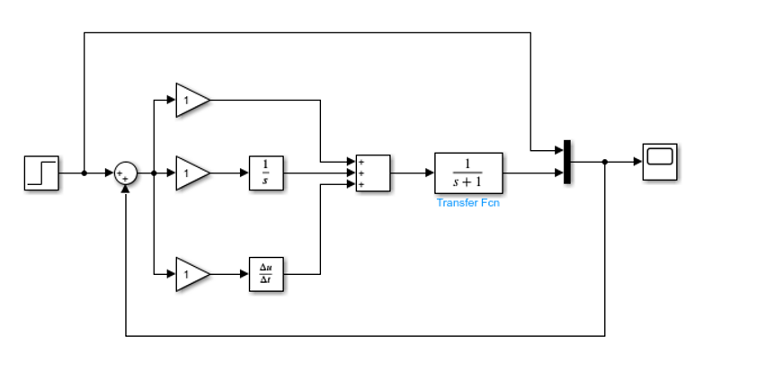
The attached image is my simulink model of the process. The transfer function for the motor is just the base simple function.