This is probably going to seem like a dumb question, but what’s the peak output current for the 18v15 Simple Motor Controller? I can see that the continuous current is 15A, but I couldn’t find info on the peak current anywhere. Maybe I need caffeine.
Background: I need a motor controller for a 6WD Dagu Wild Thumper (34:1). It’s mentioned that the motors have a stalling current of 6.6A (I read the manufacturer specs somewhere in Mandarin that say 5.5A per motor, but whatever). I understand that the rover will require 19.7A (or 16.5A) to start up.
Related question: Is 15A sufficient to drive the 6WD Thumper over outdoors terrain with about 5lb weight on it? Or would you recommend a different motor driver? I’ll be using an Arduino (Mega or Uno), and will likely use RC control, if that helps.
Quick follow-up question: How will adding a heat sink affect peak and continuous output current? I am totally new to electronics and robotics.
If a heat sink improves performance, what’s the easiest way to add it? I’ve read about heat conducting tape, but can I use small drops of superglue along the edges (so that most of the surface is free of glue) and stick it over the chip? Thank you.
The 18v15s can handle much more than 15A for brief periods of time, so we generally expect that a pair of those 18v15 Simple Motor Controllers would work fine for controlling the 6WD Wild Thumper, especially because we do not expect all three wheels of a side of the Wild Thumper to come to a complete stop at the same time for a long enough period of time to damage the motor drivers. If you think you might be pushing the limits of your Wild Thumper by operating in conditions like that, you might consider using a pair of the more powerful 18v25 Simple Motor Controllers, which can handle 25A continuously.
As for stall current: the gearmotors used in the Wild Thumper have a stall current of 6.6A when supplied with 7.2V. Since stall current is dependent on the voltage that the motor is being supplied with, 5.5A is the stall current at 6V.
Heat sinking can help increase the amount of current a motor driver can handle continuously, but it would not do much to increase the peak current that a motor driver can handle for brief periods of time. It is probably not a great idea to use super glue to mount a heat sink since the glue could be a poor thermal conductor and using it could introduce an air gap in between the two parts. It would be more straightforward to use a thermal glue or even thermal tape.
Thank you for your excellent response - being new to robotics, I learned a lot. I wasn’t aware that stall current is influenced by voltage. I’ve been looking at options for batteries and it looks like 7.2V batteries are more easily available than 6V batteries, so it looks like my rover’s stall current will be 6.6A.
That said, it doesn’t look like I will need more than 15A continuous current (over uneven terrain), so I believe that 18v15 will be sufficient (also, I do not have experience soldering, so I’d like to avoid the hassle of assembling an 18v25).
However, getting the rover moving would require 6.6 x 3 = 19.8A per channel. Which is why I wanted to know the peak output current for an 18v15. I think that a peak current of 25A or more would be ideal. Can the 18v15 supply this?
Finally, would it be better to place a heat sink underneath the controller, or on top of the large, black, square component, or elsewhere? Apologies for my ignorance; I appreciate your help!
We do not have a peak current rating for the Simple Motor Controllers (SMCs), and it is not a simple thing to specify since it could depend on many factors in a system like voltage, temperature, and duration of the spike. In general, though, we expect those controllers to be able to handle getting the 6WD Wild Thumper moving from a standstill since the 18v15 can handle several times the current you calculated for brief periods of time.
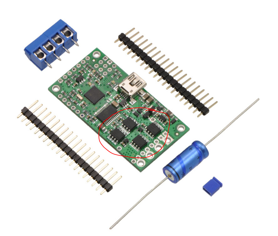
A good place for a heat sink would be the tops of the four FETs, which I’ve circled in red in the following image:
By the way, in case it was not clear: the SMCs only control a single motor, so you will need two of them. Since you are interested in RC control, I recommend reading through the Connecting an RC Receiver section of the SMC user’s guide, which also goes over configuring and connecting two of those controllers for RC control. You can find the SMC’s user’s guide under the Resources tab of its product page.