Hi,
I’m looking to buy some motors with quadrature encoders from you and I have a question.
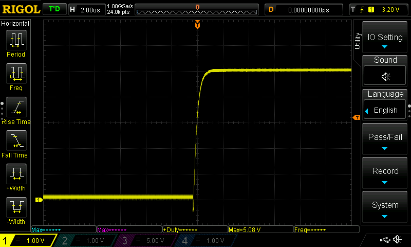
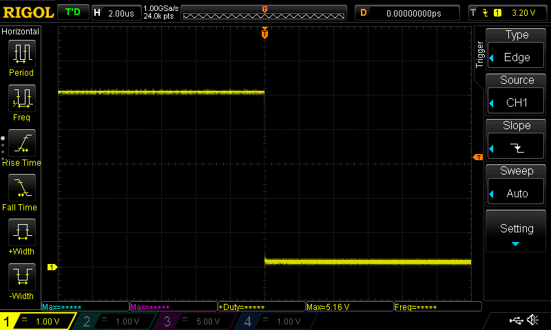
I found a few DC motors/encoders (no datasheet) laying around that have a hall effect quadrature encoder attached. I tried using these but found they generated false interrupts when connected up to my MCU. I hooked up a scope and found the encoders were taking 7us to transition when the motor was running slowly (about 1 rev/sec) and there is a little sine wave “bump” in the middle of the transition.
So I’m wondering if this is normal for a Hall quadrature encoder? Or are yours of a different type that produce a quicker/cleaner digital output that would be more compatible with hooking to 3.3v MCU’s GPIO pins?
Hello, Greg.
The hall effect sensors on our encoder boards have some hysteresis to prevent bounces like that. Here is the sample output from a Magnetic Encoder Pair Kit for Micro Metal Gearmotors board I have lying around.
You might also be interested in reading this blog post about developing those boards.
-Nathan
Thanks for the info, I added some schmitt triggers to my cheap encoders and now they work pretty well. Though since I have to build several more of these robots I think I will be buying my motors/encoders from you for the next ones, your encoders look much better!
I’ve run into one thing and I’m wondering about, I have a PID controller driving the motors and I have noticed that when I start the motors at slow speed, the initial pulse train from the encoders can be weird. Like I’ll see a one pulse on channel one and multiple pulses on channel 2, or the phase of the signals will be off making the PID controller think the motors are running in reverse. Or I’ll see a lot of pulses on one channel and none on the other which can make the PID think the motor is running way to fast.
Any of these things result in a rough startup of the motor ie: if the PID thinks the motor is running way to fast, it tries to reverse it to slow it down.
What I’m wondering is, do all encoders do this or is it just mine? Is there something I should be doing to reject these startup anomalies?
Right now I have my own interrupt handler similar to those I’ve seen in other people’s projects. Is there a particular encoder library that is better at dealing with imperfect encoders I could be using?
We haven’t run into signal issues like that with our encoders. If the frequency of the spurious signals is much higher than the frequency of the expected output, a low pass RC filter might help, though we do not have any specific advice for implementing it. We are not aware of any encoder libraries that implement any kind of filtering.
-Nathan
Hey, have you guys looked at the Hall Effect Rotary Position sensors from Allegro or AMS? These things look quite cool! They give ABSOLUTE position based on a magnet mounted on the motor shaft and a single chip you mount ABOVE it (ie: the chip is centered on the end of the motor shaft, in a plane parallel to the magnet. It measures absolute position using 4 hall sensors built into the chip.
You can read an absolute position with anywhere from 8 to 14 bit precision depending on the chip, they have a variety of different interfaces including I2C and can generate quadrature signals too if you don’t want absolute positioning.
These things would be a great upgrade to your encoders, pulse counting and interrupts not required, you can just read absolute position when you want to and use the data to calculate speed.
Here are some links
https://www.allegromicro.com/en/Products/Magnetic-Linear-And-Angular-Position-Sensor-ICs/Angular-Position-Sensor-ICs.aspx
https://ams.com/angle-position-on-axis
We have looked at sensors like that before. They are expensive and difficult to use in a modular solution because that sensor chip has to be behind the motor shaft. (It’s also a bit of a waste to use that kind of a sensor on the side before the gearbox, as opposed to on the final output shaft.)
There was a discussion a while back by some customers who were making their own modules for our micro metal gearmotors, but unfortunately, it looks like those links are not good anymore. I did a quick search on some of the Tindie and AliExpress type sites and did not find any current versions of such projects or products.
Please let us know if you build or find anything with these absolute encoders.
-Nathan
I saw $4-5 in quantity 100 which doesn’t seem that bad, particularly when you only need one chip.
I think each manufacturer has at least 10 variations of the chip and some are able to mount the chip off-axis as well.
A lot of the chips are rated to run above 20,000 rpm, so they should work well on the side before the gearbox.
For us, that is expensive for a single component. What would be a reasonable cost for you for the full sensor board, encoder disk, and mounting solution?
-Nathan
Not sure the right thing to say here, but just for the purpose of evaluating this kind of encoder I wouldn’t mind paying $20 more for the absolute position encoder compared to the standard one. Probably the i2c or SPI interface type. I think the manufacturer sells an eval board for between $20-$30. Their setup is a PCB that you attach to the backside of a motor (above the disk) with 4 stand-offs.
I wouldn’t think this would HAVE to be that much more expensive though, since you only need 1 chip and the magnet is just a simple horizontally magnetized disk instead of a multipole one.
I’m getting ready to order some of your https://www.pololu.com/product/2823 motors/encoders to replace my junky ones. Will probably mount some skate wheels between 65 and 120mm diameter for my balancing robot. Probably overkill, but should DEFINATELY work better than what I have.
Hey, I jest noticed the encoders on https://www.pololu.com/product/2823 say they have a minimum voltage of 3.5v. All my microcontrolers are 3.3v, do you think the encoders will work at that voltage?
We provide specifications like the minimum voltage because that is where we expect them to work. It is possible that some individual samples might work at lower voltages, but some might not. The encoder outputs are just outputs, and many 3.3V microcontrollers have 5V tolerant inputs, so you might be able to make a direct connection. If you do not have any inputs that can tolerate the higher voltage, you should reduce the signal levels. We have a level shifter that is overkill since it’s made for bidirectional level shifting, but it’s pretty cheap, so it might still be more convenient than getting four resistors, especially if you can use the extra channels for something else.
-Nathan
Unfortunately, a lot of newer 3.3v microcontrollers are not 5v tolerant anymore. The ESP32 is a great system for controling a robot because it’s fast, cheap and has wifi/bluetooth but all of it’s pins say 3.3v as a limit.
I can do level shifters, but was hoping to keep the circuitry simple.
Thanks for the info