Hi there,
I have two Jrk G2 24v21 motor controllers and one appears to have quietly stopped working, with no errors or visible damage. They both worked until today.
- They each drive a Gobilda 5202 Series Yellow Jacket Motor (SKU: 5202-0002-0001).
- The controllers are powered in parallel by a single Bioennopower 12V battery (SKU: BLF-1212A).
- They’re connected by USB cables to a Windows laptop (tested new cables).
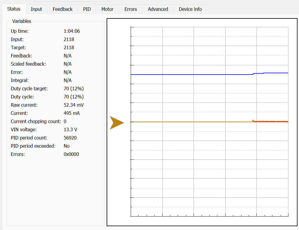
Both controllers are still recognized by the Jrk G2 Configuration Utility but the upset controller doesn’t show any current or turn the motor when a target is set. I’ve tested both controllers with both motors: both motors turn and show current draw when connected to the working controller, which shows VIN of 13.3 V.
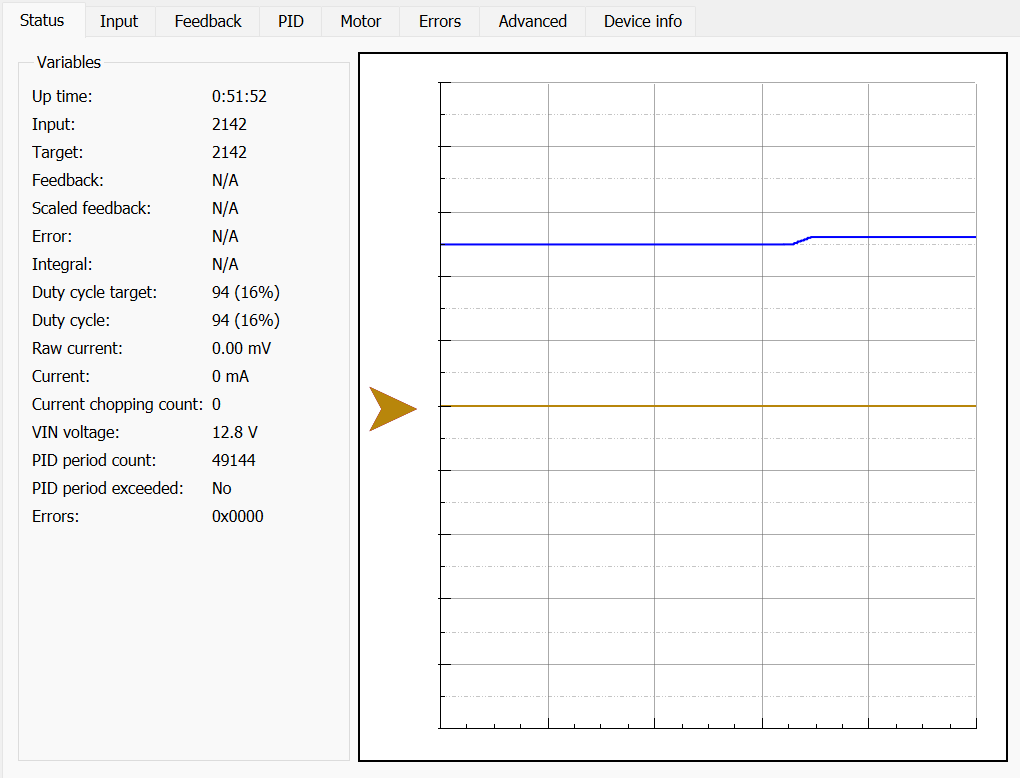
Both controllers do nothing and show 0 mA current when connected to the upset controller, regardless of where the target is set, and this controller reports VIN of 12.8 V. Not sure if 0.5 V difference is relevant but just noticed the difference.
I’ve checked the wiring and the connections seem good (famous last words).
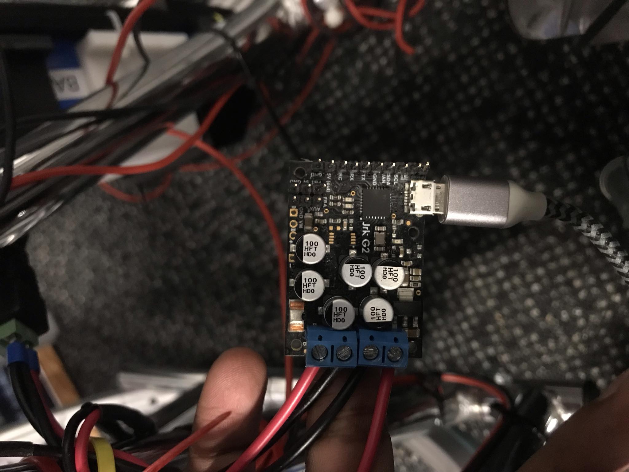
Working Controller:
Upset Controller:
Do you have any suggestions for troubleshooting?
Cheers
Hello.
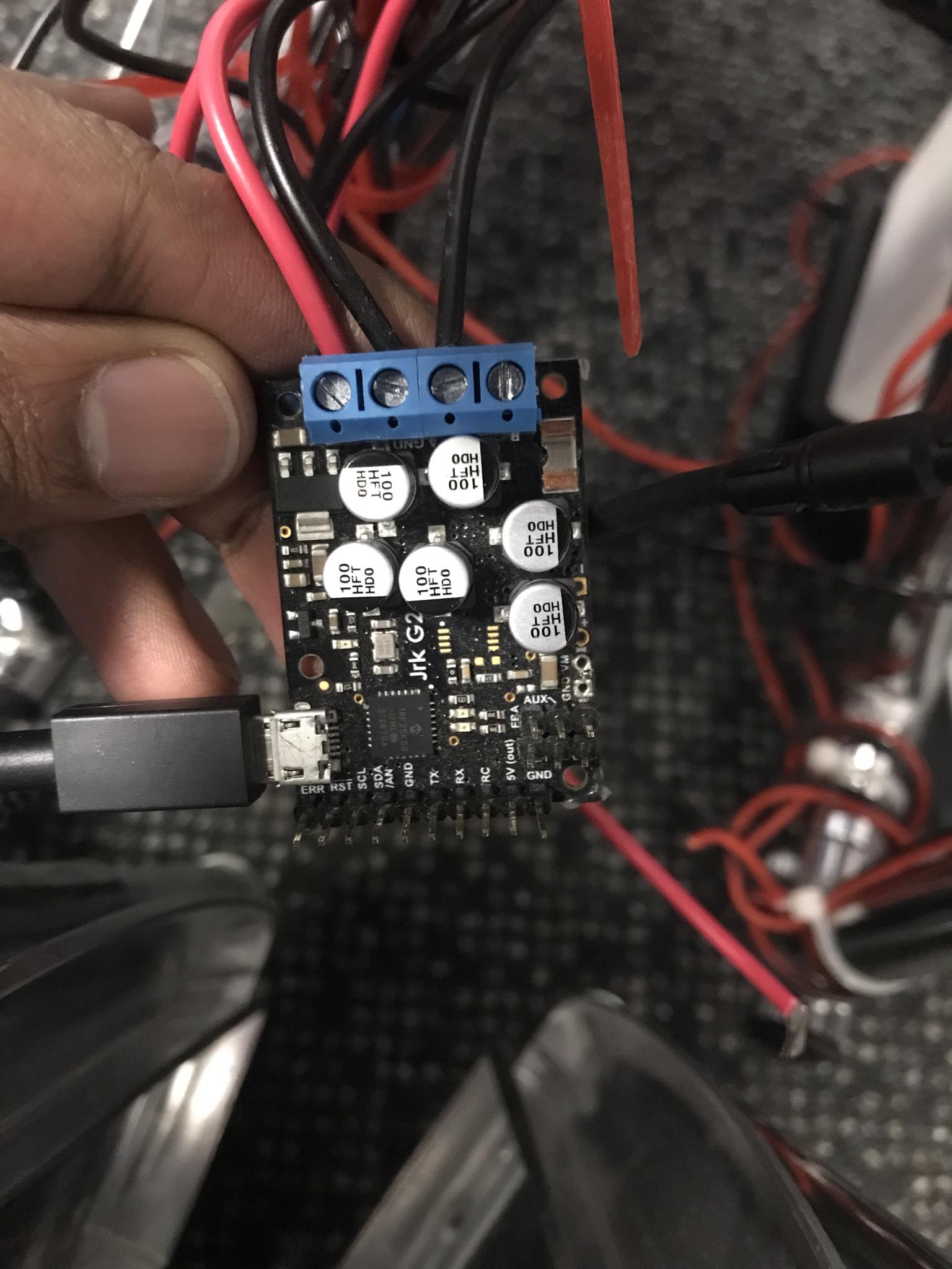
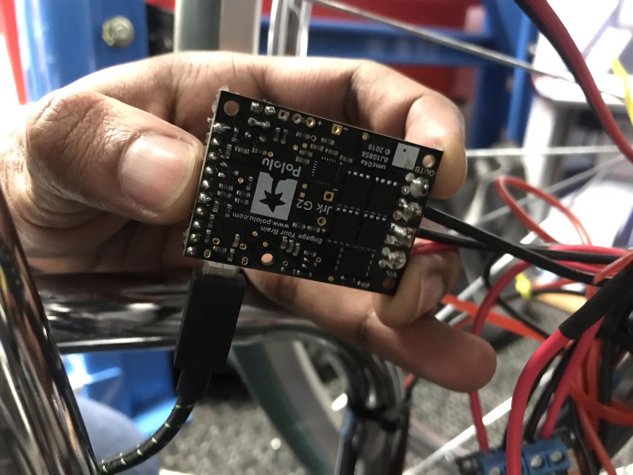
Could you post some pictures of your setup that show all of your connections as well as some close-up pictures of both sides of the problematic board? Also, could you post a copy of the Jrk settings file from each controller, clearly indicating which ones came from which controller? You can save a copy of the settings file from the “File” drop-down menu of the Jrk G2 Configuration Utility while the particular controller is connected.
Brandon
Thanks Brandon, images and settings files are below (please forgive the slow reply).
Upset controller: jrk_settings - 1.txt (2.0 KB)
Working controller: jrk_settings - 24v21 #00408151.txt (2.0 KB)
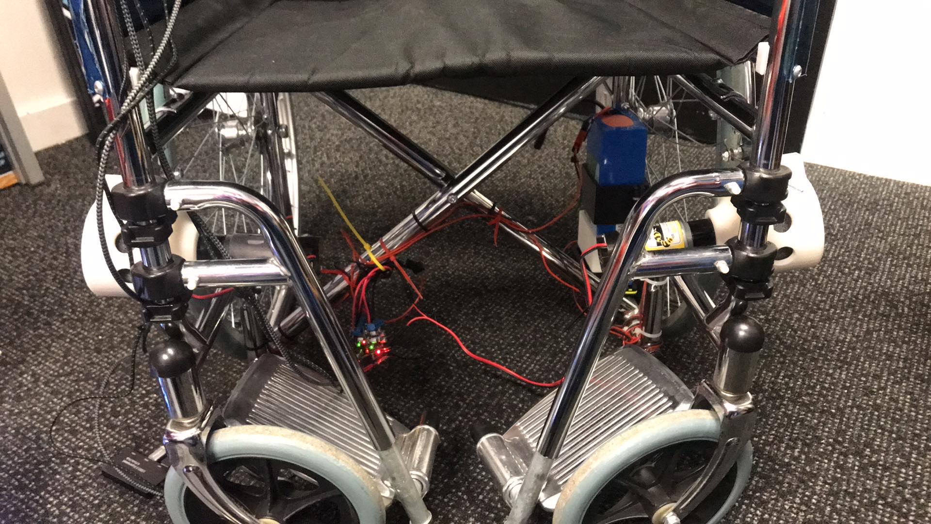
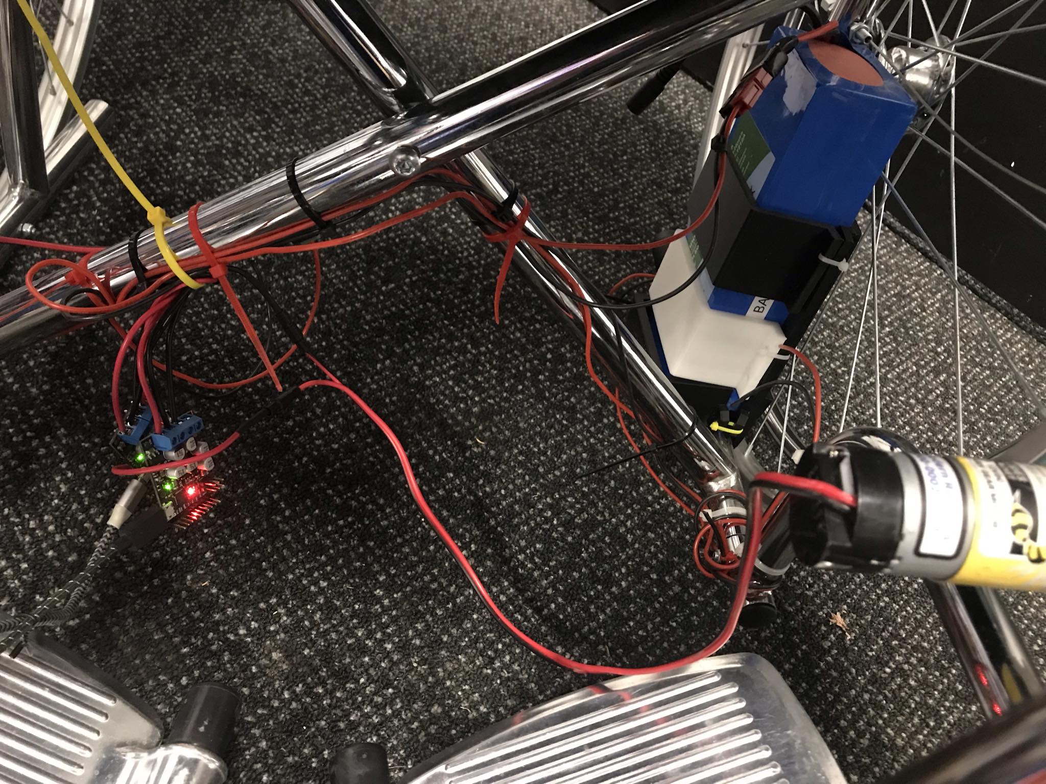
Setup: (powering an electric wheelchair)
Let me know if you need anything else.
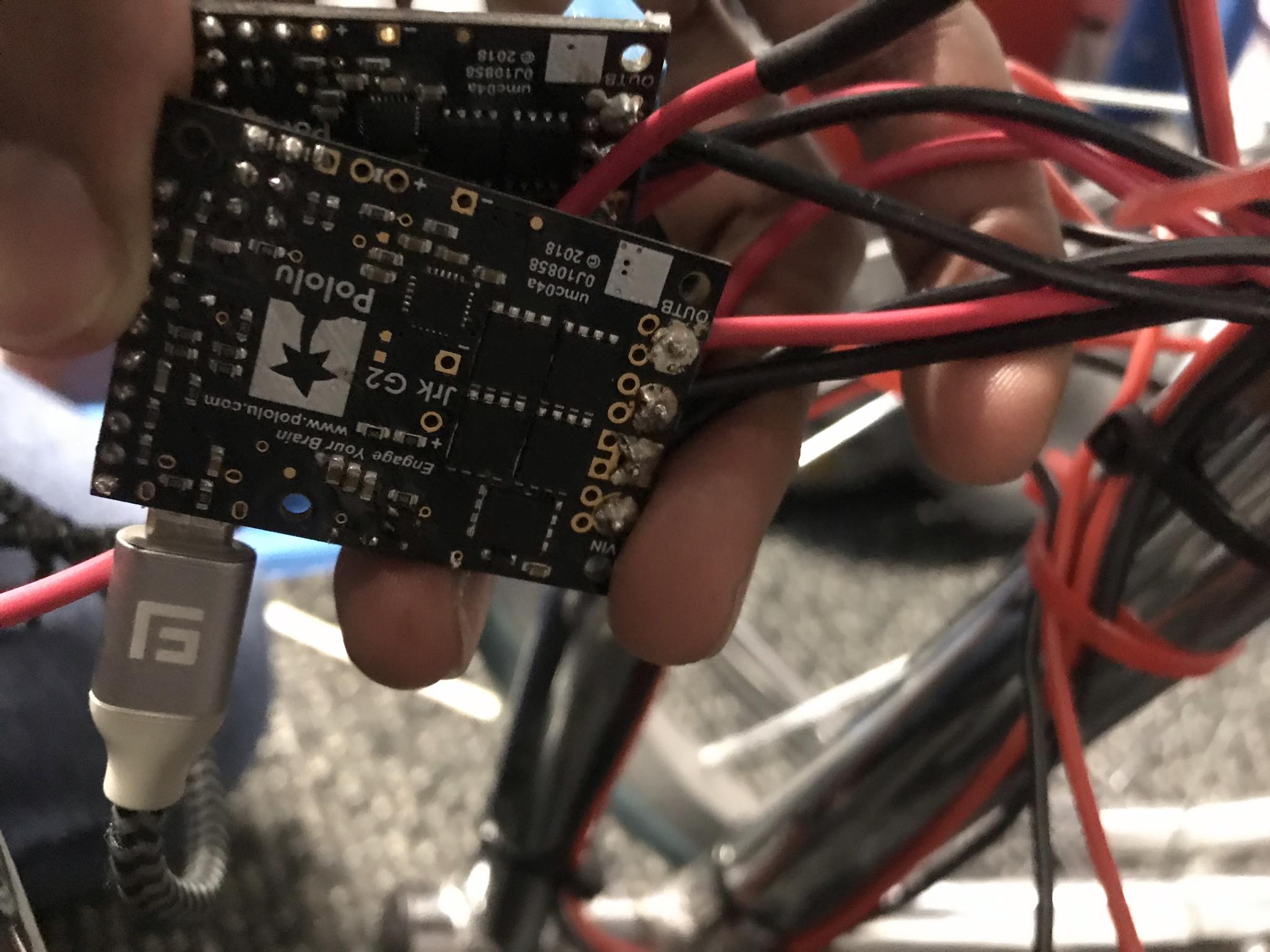
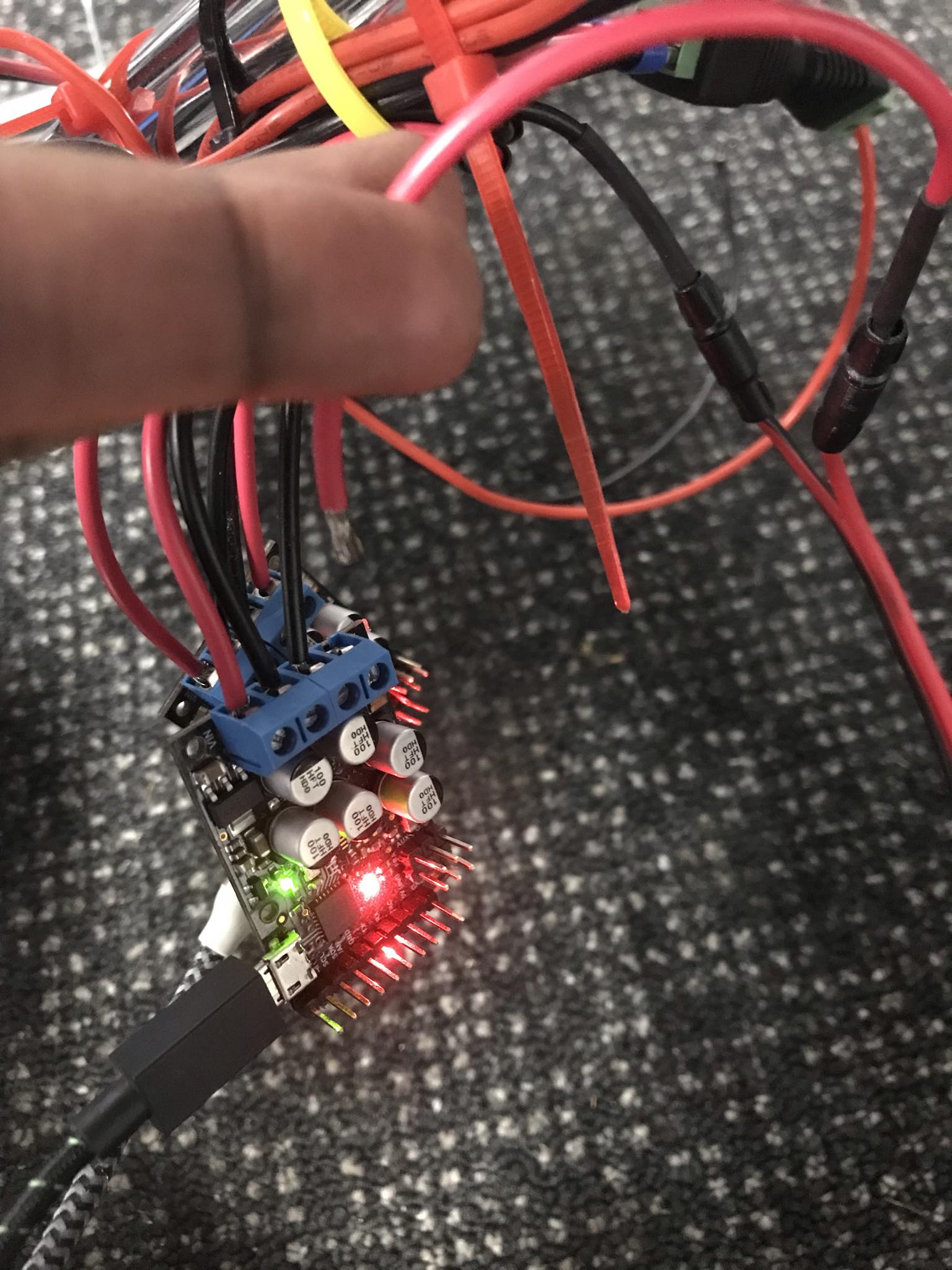
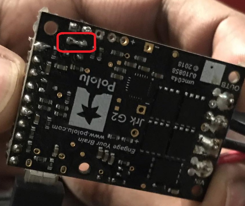
It sounds like the driver IC is damaged or not powering on. There are a couple of things in your pictures that are concerning.
- It is hard to tell from the angle of the picture, but it looks like several of your solder joints are suspect; in particular, there might be a solder bridge shorting the AUX and 5V pins together:
- It looks like your boards are just hanging loosely next to each other from their power and motor wires, and they could easily touch and short together.
Between those two situations, it is probably more likely that the boards touching together would cause that kind of issue, but it is not entirely clear if either of those actually caused the damage or if it was something else entirely.
Brandon