
Having successfully assembled and programmed a basic mobile robotic platform using the Pololu RP5 Chassis, the Pololu Qik-2s9v1 motor controller and a Netduino micro controller, see my forum post at https://forum.pololu.com/t/qik2s9v1-motor-controller-and-netduino-initial-results/2551/1, my next step in building an autonous robot was to add a means of obstacle avoidance. After looking at the options available I selected one of the Maxbotix LV-MaxSonar ultrasonic range sensors. The Maxbotix sensors are relatively low cost, provide a choice of several beam widths with tradeoffs in sensitivty and side object detection and provide analog, serial and PWM outputs simultaneously. Another
feature I liked about the Maxbotix sensors is that they can be powered up and allowed to run continuously providing a range reading approximately every 49ms, there is no need to provide them with a start pulse to acquire a range reading although it is an option.
In reading through a number of user postings as well as the FAQs on the Maxbotix website, the consensus seemed to be that the analog ouput was the easiest to use. As such, I wired up my Netduino for the Maxbotix in analog mode. This required jumpering the 3.3v output of the Netduino to the Netduino Analog Reference input, AREF, providing 3.3v to the Maxbotix sensors and running a wire from the Maxbotix analog output pin to one of the Netduino’s analog input pins. At 3.3v, the Netduino uses 3.3v logic although the digital inputs are 5v tolerant, the Maxbotix analog interface provides approx. 6.4mv/inch. After a little bit of work I had a C# class to support the Maxbotix sensor which provided the distance in inches to objects targeted by the sensor. It should be noted that a bit of arithmetic calculation was involved to do all of this.
Experimenting with this setup I noticed that with both the sensor and the targeted object completely stationary the repoted distance would vary continuously, often several inches over distances of three feet or less. The basic problem, and one reported by most users, is that the analog output is easily affected by any electrical noise. In the FAQs on their website Maxbotix provides a solution to the analog noise problem which involves the addition of an rc circuit at the anlaog input on the Netduino to filter out noise. I tried this solution but it really didn’t make a meaningful difference - and that was before I started running the DC motors in the chassis. My next thought was to utilize the serial output of the Maxbotix.
The serial output of the Maxbotix range finder is a rather strange beast. According to Maxbotix it uses RS232 format but with voltages running from 0 to Vcc. After a little research and thinking about it I realized that basically the Maxbotix was outputting an inverted data stream: 0s were sent as Vcc and 1s were sent as Vss. If I wanted to utilize the serial output, I was going to have to invert the datastream from the sensor. I searched the Internet for information on inverters and after a lot of reading I came across a very nice CMOS IC from Texas Instrumens: the CD4049BU hex inverting buffer. The IC provides six pairs of inputs and outputs, input a 0 bit and it comes out a 1 bit and vice versa. The IC itself cost $1.49, so I felt comfortable ordering three of them in case of mistakes.
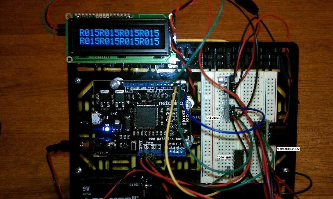
As mentioned, the Netduino digital inputs are 5v tolerant so I ran 5v to Vcc on both the Maxbotix and the CD4049BU. I ran a wire from the TX pin on the Maxbotix to an input on the CD4049BU and another wire from the companion output of the CD4049BU to the COM2 serial input on the Netduino, the COM1 serial port on the Netduino runs the Qik-2s9v1 motor controller. For test purposes I ran the COM2 serial output through an FTDI cable to a USB port on my PC to drive an ASCII terminal program. I powered everything up and it all worked very nicely - the screen on the ASCII terminal program filled with a sequence of “R047.” “R” marks the start of a measurement from the Maxbotix and the next three characters represent the distance to the target in inches - no user calculations required. Testing showed that the serial output was completely stable. If I left the sensor stationary and pointed it a stationary target, the distance reported was constant.
Note - the serial I/O class I developed is general purpose and can be used for any type of serial I/O. If anyone is interested in the source code, please contact me. It is a little too long and off topic for posting here.
The next job was to write some code to make use of the distance sensor to turn the robot in order to avoid running into obstacles. It sounded easy but a lot of testing of different approaches proved it was anything but. In fact, in order to better understand what was gong on I attached an LCD display to the chassis and wired it into the COM2 serial output port to observe the distance being reported as the robot reacted to obstacles. Below is an image of the current state of construction of the robot platform.
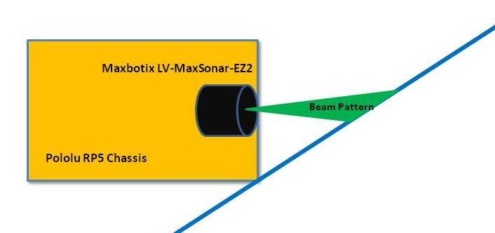
The first approach to basic obstacle avoidance was to have the robot turn right when it detects it is within 12 inches of an obstacle. Since distance is reported continuously I let the robot turn until the reported distance was greater than 15 inches at which time it would start to move forward again. The first issue I noticed is that when approaching an obstacle such as a wall at a sharp angle a corner of the chassis can jam against the wall. The reason for this is that the ultrasonic beam is not being reflected back directly into the sensor. Some of the beam is reflected off at an angle missing the sensor and I would hypothesize that the sensor is detecting mulitple arrival times for the beam. I’m not sure if the sensor filters for this situation but I am sure that the reading is not very accurate in this situation - it didn’t appear to be while following the robot around and monitoring the LCD readings. The diagram below best explains the problem.
I tried several different algorithms, some involving turning first to the right, then to the left. In other cases after a certain number of right and left turns backing up and trying again. Varying the speeds of the turns and slowing down when approaching an obstacle, etc., etc. What I finally concluded is that obstacle detection and avoidance, at least using my current platform, is dependent on: forward speed, distance sampling rate, turning speed and sensor height. All of the algorithms I eventually started to fine tune allowed the robot to move around my living room without running into any obstructions, including two very curious cats. However, the robot tended to travel in circles of ever increasing radius. It never successfully navigated from one side of the room to the other in anythng resembling a realitvely stratight line.
After thinking about it all I realized that to approach an obstacle, go around it and continue once more in a straight line is going to require the ability to follow the shape of the obstacle, determine when to turn back onto a straight line and determine exactly what direction that straight line should be in. This brings up thoughts of side facing Maxbiotix detectors or perhaps an IR detector since moving around an object would be done at short distances. I’m also wondering about the possibility of a qyroscope to measure yaw as another navigational aide. The joy of all this is that it is fun to think about, research and the bits and pieces to make it
all go are relatively inexpensive.
If anyone has any additional ideas or insights, I would be very interested to hear from you.