I’m using a Xavier NX board with the 40 pin expansion, when I run the detect I2C script on it, it does not detect the TIC 249 I have connected.
I can confirm via an oscilloscope that a signal is sent out, and that all signals are at the correct values (Xavier: SDA3.3V, SCL3.3V, GND0V and TIC: SDA5V, SCL5V, GND 0V) and connected together.
The TIC is set to Serial/I2C/USB mode, with a baud of 100,000Hz (The same as the NX’s Output).
I am not currently trying to run the Polulu software for the device to control it, just to detect it on the I2C port.
Do you have any suggestions as to why this isn’t working?
Hello.
Could you post some more information about your setup, including pictures that show all of your connections as well as how you are powering the Tic? Additionally, could you post a copy of your Tic settings file? You can save a copy of the settings file from the “File” drop-down menu of the Tic Control Center while the controller is connected.
Brandon
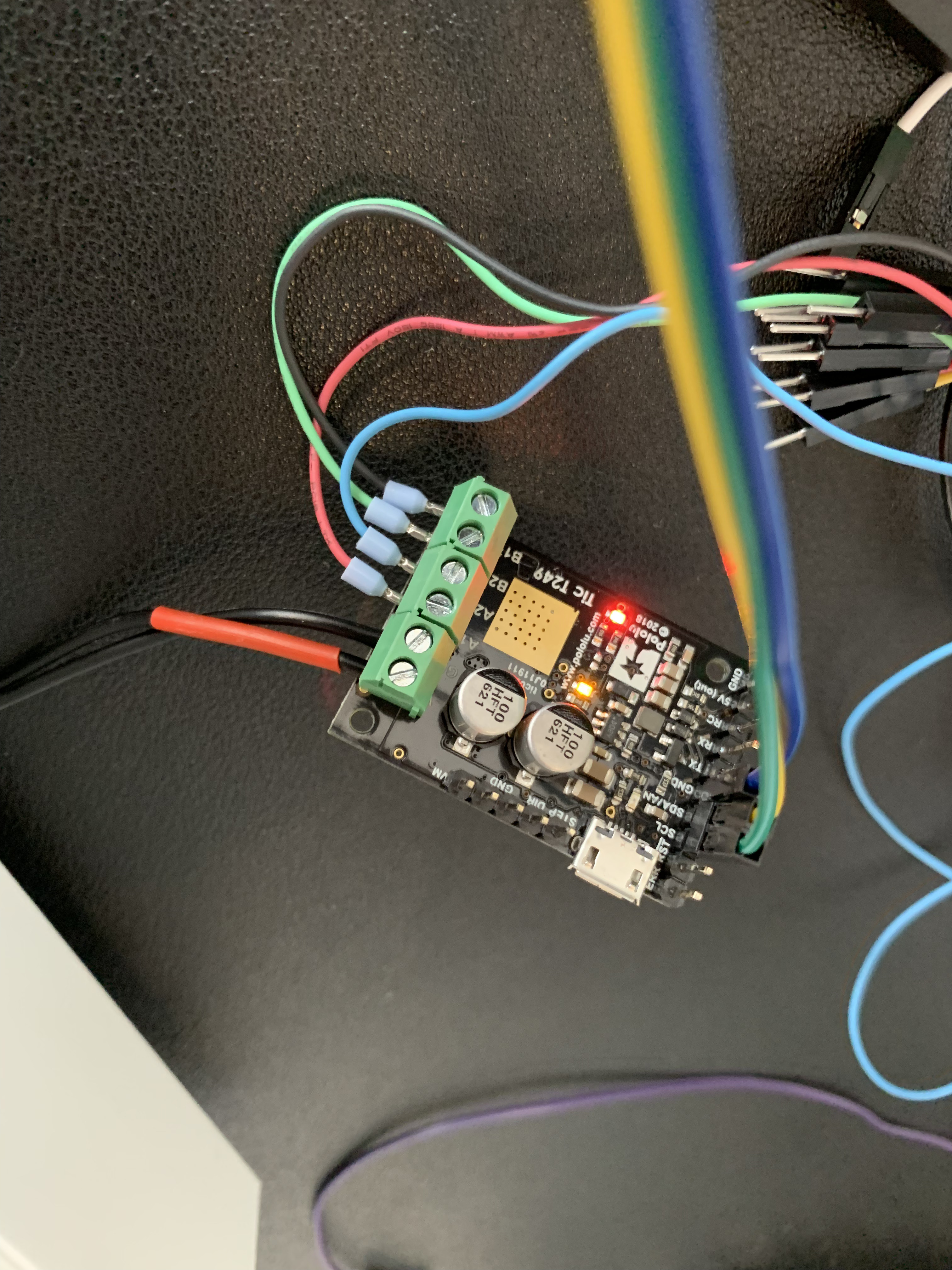
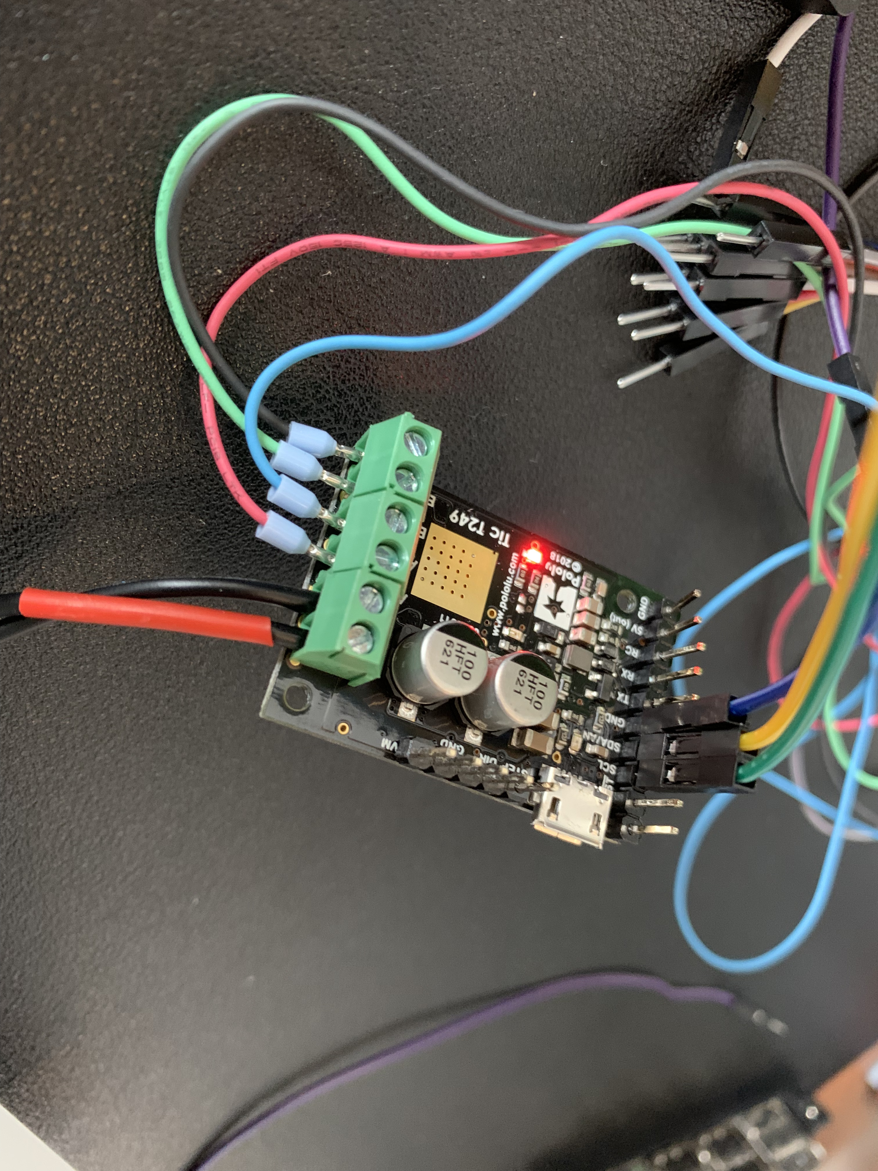
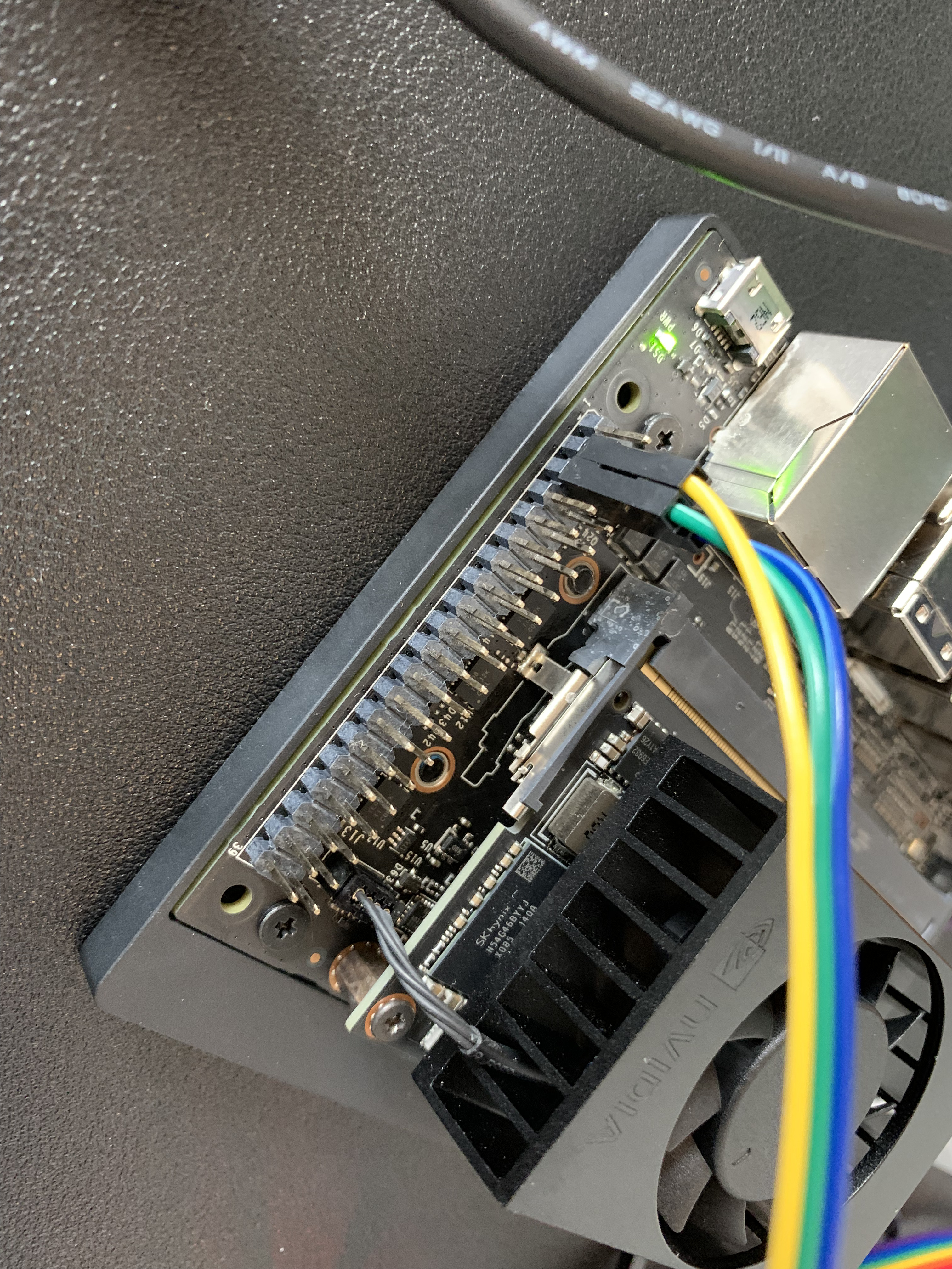
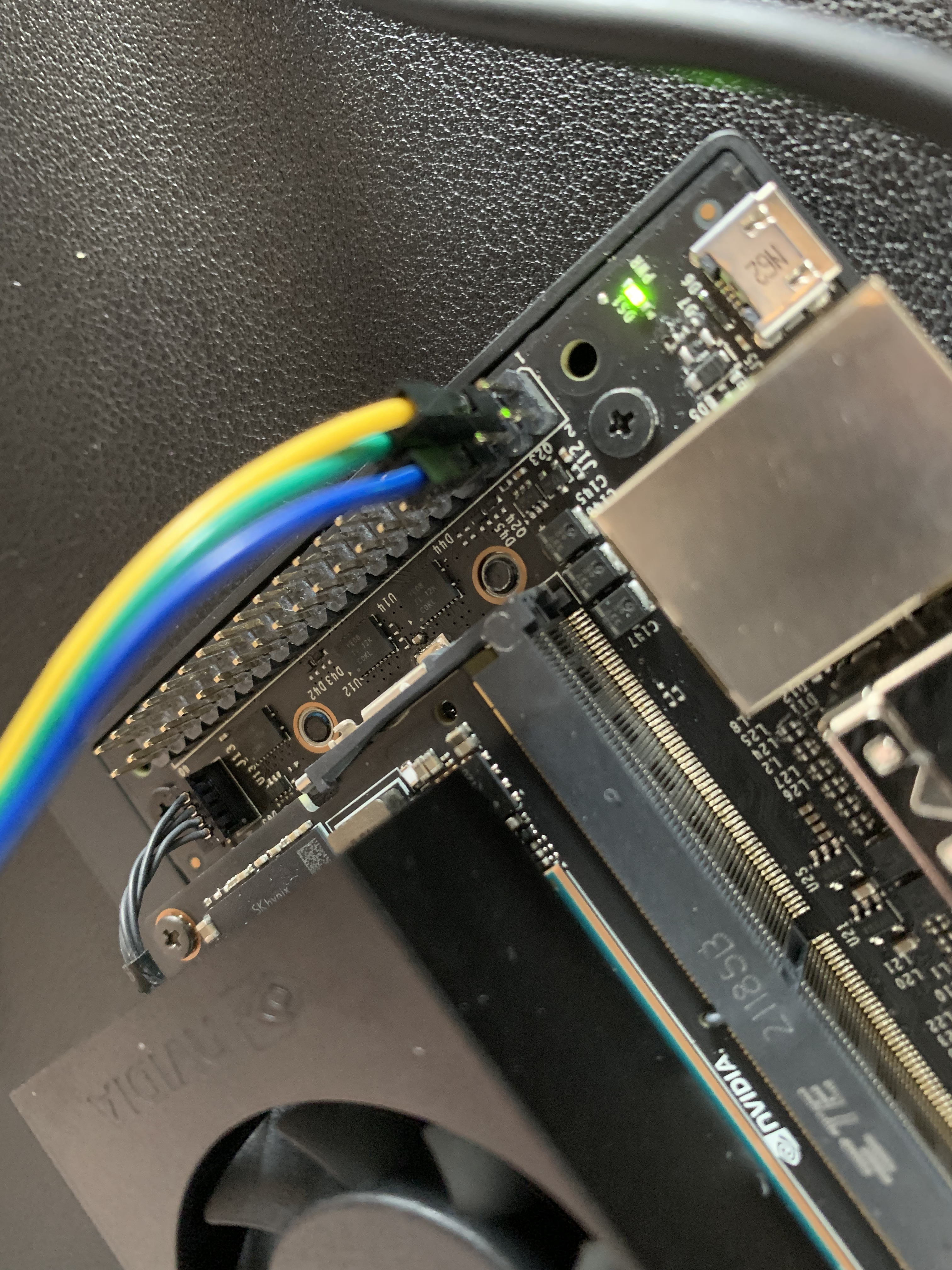
Hi,
here is the setup.
The input power is 12V (up to 4A).
tic_settings.txt (1.4 KB)
Thank you for the additional information and pictures. It looks like you have the SCL and SDA pins configured as “User I/O”. To use the I2C interface, you should have those configured as “Default”, under the “Advanced settings” tab of the TIc Control Center.
Please note that by default these pins are pulled up to 5V. I am not very familiar with the Nvidia Jetson Xavier NX, but it is common for microcontrollers to have a diode going from each I/O pin to its logic supply, which clamps the voltage on the pins and prevents the pull-up resistors from pulling the voltage too high. If your controller does not have those clamping diodes (or if you want to be extra safe and not rely on the clamping diodes), you can disable the Tic’s pull-up resistors by, changing the pin configuration of SCL and SDA pins to “Serial”, and making sure the “Pull-up” checkbox for each pin is not checked. Then, you can add your own external pull resistors to 3.3V instead.
If you still have the problem after changing the pin configuration settings, could you post an updated settings file as well as a copy of the simplest, but complete code that exhibits the problem?
Brandon