Nonlinear relatioonship between motor encoder speed and PWM

Hi, I’m Nathan. You may remember me from such posts as Logic Level Shifter for reading motor encoders and VNH5019 Additional Capacitor. I’m currently testing out the encoders on my 30:1 Metal Gearmotor 37Dx68L.

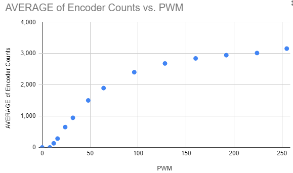
I wrote a test program to compare the PWM value against the motor speed measured by the encoder. I was expecting a linear relationship, but I found a logarithmic looking one. Below is a graph of my results, showing the average encoder counts per second against the Arduino PWM value (0-255).
image

My questions are:

  1. Is my expectation of a linear relationship correct, or is the nonlinear relationship as expected?
  2. If my linear expectation is correct, can anyone see a problem with my test?
  3. Why is the top speed ~3150 counts per second instead of ~2640?

Any help or advice would be greatly appreciated.

I have the following connections between my components and the Arduino Nano 33 IoT microcontroller:

  • D5 → IN1 on VNH5019
  • D7 → IN2 on VNH5019
  • D6 → PWM on VNH5019
  • 3V3 → VDD on VNH5019
  • GND → GND on VNH5019
  • 5V → Encoder Vcc on motor
  • GND → Encoder GND on motor
  • D2 → Encoder A output on motor (via logic level shifter)

VIN on the VNH5019 is connected to a 3S 18650 battery, which is currently outputting 12.3V. As per my previous post, I measured 12V across the additional capacitor on the VNH5019.

:information_source: Note that I also tried replacing the logic level shifter with a 1k/2.2k resistor voltage divider, but I got the same results.

My Arduino code is below:

const int ENCODER_A = 2;
const int ENCODER_B = 3;

const int IN1 = 5;
const int IN2 = 7;
const int PWM = 6;

const int MOTOR_SPEEDS[] = { 0, 8, 12, 16, 24, 32, 48, 64, 96, 128, 160, 192, 224, 255 };
const int MOTOR_SPEEDS_LENGTH = 14;
const int LOOP_MICROS = 1000000;

volatile int pulseCount = 0;
long loopEndTime = 0;
long measurementTime = 0;
int speedIndex = 0;
int speedLoopCount = 0;

void setup() {
  pinMode(IN1, OUTPUT);
  pinMode(IN2, OUTPUT);
  pinMode(PWM, OUTPUT);

  Serial.begin(2000000);
  while (!Serial);

  pinMode(ENCODER_A, INPUT_PULLUP);
  pinMode(ENCODER_B, INPUT_PULLUP);
  attachInterrupt(digitalPinToInterrupt(ENCODER_A), encoderPulse, RISING);

  measurementTime = micros();
  loopEndTime = micros() + LOOP_MICROS;
}

void encoderPulse() {
  pulseCount++;
}

void loop() {
  if (speedIndex >= MOTOR_SPEEDS_LENGTH) {
    analogWrite(PWM, 0);
    while (true);
  }

  int speed = MOTOR_SPEEDS[speedIndex];
  speedLoopCount++;
  if (speedLoopCount >= 15) {
    speedIndex++;
    speedLoopCount = 0;
  }

  //control speed 
  analogWrite(PWM, speed);
  //control direction 
  digitalWrite(IN1, LOW);
  digitalWrite(IN2, HIGH);

  noInterrupts();
  long now = micros();
  int pulseCountValue = pulseCount;
  pulseCount = 0;
  interrupts();

  long measurementInterval = now - measurementTime;
  measurementTime = now;

  Serial.print(speed);
  Serial.print(",");
  Serial.print(measurementInterval);
  Serial.print(",");
  Serial.println(pulseCountValue);

  while(loopEndTime > micros());
  loopEndTime += LOOP_MICROS;
}

The nonlinear relationship is expected. In addition you will notice that there is a minimum PWM value required for the motor to start moving.

For any PWM value the speed will also depend on the motor load. If your goal is to have the motor shaft rotate at a specific speed, you need to implement feedback control (i.e. use PID code).

2 Likes

Thanks Jim. I don’t really know why I was expecting the linear relationship, but glad to know that my results are valid.

Does anyone have any thoughts about why the max speed (3150 pulses per second) is ~20% faster than the 2640 value Patrick calculated here: Logic Level Shifter for reading motor encoders?

No two motors of the same type behave exactly alike. There are differences in bearing friction, magnetic field strength, etc. In turn those lead to differences in free running RPM at the same power supply voltage.

Here is some material I posted in 2007, using an obsolete Pololu Orangutan motor controller and a small robot with wheels powered by servos modified for continuous rotation. If you are really interested in (nearly) linear rotational speed versus PWM behavior, consider using PWM brake mode for the motor driver, if available.

PWM mode tests

Although 255 motor speed steps are permitted, the gears are stiff enough that even when held off the ground, the wheels on my test rig don’t rotate until the PWM setting is about 35, and little difference is seen for increments of 1 step. I chose to monitor free rotation of the robot wheel, that is, the robot did not need to drag itself around. Needless to say the LCD display is hard to read when moving! Besides, everyone’s robot will behave differently.

I measured the overall current draw of the entire robot (Orangutan plus motor controller plus WheelWatcher) by a multimeter in series with the battery leads. With the motors off in “coast mode” about 60 mA was consumed. With motors off in “brake mode” about 120 mA was consumed, due to ~60 mA base current for the output transistors in the motor driver chip. Maximum current draw for “free air” rotation (right wheel only) was around 250 mA in brake mode PWM. The current draw is of course higher if the robot is running on the ground.

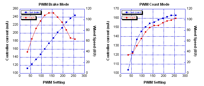
For brake mode , the wheel speed is very linear with the PWM setting but the current consumption is generally high and very nonlinear with the PWM setting. Graphs of the results are posted below. As you can see, the current draw is highest when the motor is running at about half speed. This makes perfect sense: for half of the PWM cycle, the rotational energy is being dissipated by the braking action. However, the speed setting is quite robust, that is, low speed performance is good, and the robot maintains its speed rather well if a bit of resistance is applied to the wheel. Why this should be so is less obvious, and it is not true for coast mode.
pwm_results

For coast mode , the wheel speed is a nonlinear function of the PWM setting, and tops out at well below PWM setting=255. The current draw at low to intermediate speeds is quite a bit lower than with brake mode, but about the same when both are maxed. However, at intermediate speeds, the wheel rotational rate is not robust and slight resistance applied to the wheel causes it to slow down rather quickly. In the graphs at right, wheel speed is in arbitrary units (AU).

Preliminary conclusions: brake versus coast mode

For simple PWM speed control, brake mode has better linearity of speed versus PWM setting and speed is maintained reasonably well with changes in wheel motion resistance. However, current draw is high. With coast mode, current draw is much lower at intermediate speeds, but the speed is a nonlinear function of the PWM setting. Also, the speed depends strongly on resistance to wheel motion. However, if the speed is actively controlled by a PID algorithm, “coast mode” should be superior as the power draw is lower.

2 Likes

Thanks for the additional information. Looking at the page for my motor driver, I don’t see any mention of a brake mode. I am planning to add a PID controller to control the speed of the motors (to keep my balancing robot upright). This was my first attempt at using an encoder, so I wanted to check that my results are on the right track.

I understand that each motor will have slightly different characteristics, and I’ve observed that in my testing. I have 2 of the 30:1 gearmotors and one has a deadband of ~10 and the other of ~12 (i.e. this is the minimum PWM value before the motor moves at all). Also, the encoder count readings of one motor are ~80 counts per second less than the other motor.

If the 20% higher than expected top speed can be explained by differences in manufacturing, I’m ok with that. I just wanted to check that there wasn’t a problem with the way I was measuring the encoder pulses.

Hi, Nathan.

Unfortunately, the VNH5019 only really operates in drive/coast mode. Page 14 of the VNH5019 datasheet has a truth table and above that a description of how the PWM input controls the outputs. When the PWM pin is low the outputs are floating (this is what defines coasting) and when the PWM pin is high, the state of the IN pins determines whether OUTA and OUTB are high or low. It is possible to supply a PWM signal to one of the IN pins instead and get drive/brake operation, but those pins are much slower to respond, so that is only viable up to a few hundred Hertz.

The variation you are seeing in top motor speed could be explained by normal motor variation.

-Claire

1 Like