I’m using JRK G2 21v3 motor controller for a diesel engine fuel governor application. Suprisingly, it works very well with minor issue outlined below.
I observe some RPM oscillation at idle speed when there is no load on the engine shaft. Therefore, I would like to minimize the rpm oscillation of the engine. The oscillation can be minimized by decreasing the ‘P’ and ‘I’ values. However in this case, the engine stalls if the load on the engine shaft increases. Consequently, I can not decrease the ‘P’ and ‘I’ values too much.
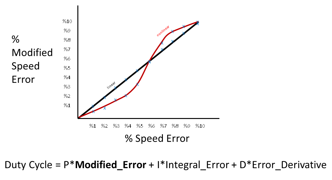
What I need is a nonlinear modification of the speed error. For example, if the actual speed error is %5, then the PID controller will see this as a %3.2 speed error and the PID algorithm will use the modified speed error. I tried to illustrate the case in the figure below.
I would like to set this nonlinear modification parameter table up to %10 percent speed error. Is it possible to implement this in the firmware? As an engineer, I feel that it is doable and I know how to modifiy the PID algorithm but can’t modify the firmware code since I don’t have it. How can I get assistance from Pololu in this respect?
The Jrk G2 controllers do not support a nonlinear error modification the way you described it. Custom firmware to do that is likely possible, but it would cost at least a few thousand dollars. If that is worth it for your project, please email us with more details including your target schedule and what you mean by % error.
Separately, if you would like help troubleshooting your current system in the meantime, we would be happy to help. For example, it might be possible to tune the PID coefficients more and improve its response. If you would like troubleshooting help, could you post more specific details about your application and the problem you’re having? For example, some specific examples of what happens at certain target values and a copy of your Jrk G2 settings file would be a helpful starting point. You can save a copy of your Jrk G2 settings file from the “File” drop-down menu of the Jrk G2 Configuration Utility while the controller is connected.
Thanks for your prompt reply and helpful suggestions. Unfortunately, my project is not funded, I try to design an electronic engine governor on my own using modern mcu and hardware. JRK G2 21v3 is one of the hardware I picked for this experimental application.
I don’t have any problems with tuning PID coefficients so far. In ship diesel engine governing application, the problem arises due to the nonlinear torque-fuel characteristics of the engine. The JRK (PID) controls the fuel actuator in my application. The goal is to keep the RPM steady at desired target RPM by regulating fuel supply. The tachometer (proximity sensor on the crankshaft) provides the actual revolution count on the feedback input of JRK G2 21v3. At low RPMs (100-400RPM) the engine consumes more fuel than it consumes at nominal RPMs(600-800RPM). Therefore, I adjust PID values dynamically over serial via external microcontroller according to the desired target RPM (using RPM-PID lookup table).
On the other hand, when ship’s clutch is engaged on the crankshaft, the engine load increases and the RPM tends to decrease. The external microcontroller detects this decrease in RPM (asking feedback value of JRK periodically over serial) and acts to compensate the engine speed decrease by increasing the P and I values step by step until RPM falls into target RPM range.
To provide smooth and stable engine operation, the engine runs in droop mode. This means the actual engine revolution is always below the applied target RPM so that the PID algorithm outputs a continuous duty cycle (never falls to zero). Otherwise, the JRK output would be ceased when actual RPM exceeds target RPM and this would cause intermittent fuel supply to the engine resulting in revolution oscillation.
The problem in my application is the engine lag (response time of the engine with respect to a change in the fuel supply) and I think this can be solved with nonlinear speed error (target and scaled feedback difference in terms of JRK terminology) modification. The rationale with the above figure is that when the actual error is minimized enough, the modified error is negligible (the P x Modified _Error product will cut down fuel input and the engine rpm wont go up further) and when the error is increased (due to increased load e.g. clutch engage) then the modified error is exaggerated (the P x Modified _Error product will increase fuel input and the engine rpm will ramp up quickly to the desired value). What I need is similar to the ‘Deadzone’ feature of JRK but somewhat different.
My definition of the percentage speed error is (assuming a single rotation direction):
%speed error = abs(target speed - scaled feedback) /2048
I wonder if you really need to change the Jrk’s PID values dynamically over serial using an external microcontroller. It sounds like you have set the Jrk’s “Feedback mode” to “Frequency”. In that mode, we recommend setting the Jrk’s integral coefficient to a non-zero value. When the measured RPM is below the desired RPM, the scaled feedback will be below target, so the Jrk’s integral variable will decrease, which causes the PID algorithm’s output to increase, which should generally increase the speed of the system. All of this happens without the intervention of an external microcontroller. Is there something special about your diesel engine governing application that makes that insufficient?
You can find more info about how to set up PID coefficients in the “Setting up frequency feedback” section of the Jrk G2 user’s guide.