I’m not getting any measured voltage from the A1, A2, B1 or B2 pins and I’m not able to measure the VREF from the via or the potentiometer. Attached is the code.
I plan on powering it through an 11.1v battery but I’m only powering it from my computer for the moment whilst I try and get things working.
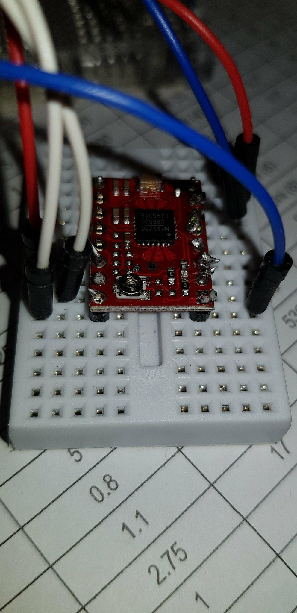
Closer up image of the driver on the bread board. The solderings are pretty shonky (I didn’t have a soldering iron that came to a sharp point, but I tested the connections and they seem to be fine. Not getting voltage from the pins at the rings either.
If you mean the 5V output, that could quite quickly smoke the internal regulator on the Arduino, or at least cause it to shut down. Very bad overload for the USB port, too.
Power the driver with a power supply of 10 V or higher and providing at least 2 Amperes. 18 Watts is the absolute minimum for full motor power.
The driver won’t work properly with that motor when powered by 5V, because the motor winding resistance of 8.6 Ohms is too high. Hence I suggested 10V minimum for the motor power supply.
The solder connections look dangerous, and if an accidental short circuit occurs, that would cause a serious problem with a high current power supply.
You should definitely get a new, fine tipped solder pencil.
Possibly the wiring is incorrect, or bad solder connections. I can’t make sense of the photos.
Also, breadboards can’t handle the current required by motors. You really need to solder the motor wires directly to the driver board, or use high current pins and connectors.
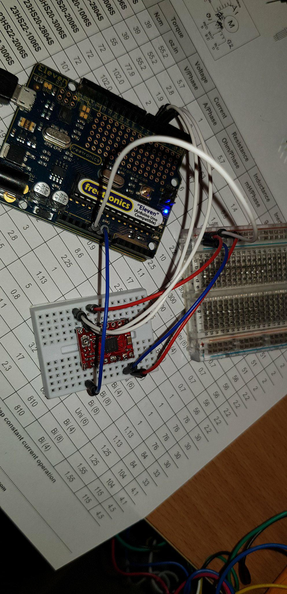
I’ve got pin 5 connected to step, pin 6 connected to dir with the code “Stepper myStepper(200,5,6);”
The 5V supply from the Arduino to the sleep pin on the driver (I read that needs a HIGH value so that the driver can run)
Bottom right ground to ground on the arduino, top right ground to ground on the battery. VMOT to the positive end on the battery and that’s about it for the wiring.
I can see a voltage varying from 0 to 5 on the step connection, and a voltage varying from 0 to 2.5 on the dir connection. I’m not sure exactly how the arduino is meant to connect to the driver.
The sarcasm is certainly welcome. Yes I have studied it and I’m only getting frustrated that I may be missing something small, what I was referring to was the digital pins that are connected to step and dir. Do they interface with the stepper.h library on Arduino? I’m not too certain on how the Stepper myStepper(200,5,6) works in the coding. I’ve tried to look up in the references what the 5 and 6 should be connected to but can’t seem to find anything specifically addressing them.
I don’t use stepper motor libraries and had not realized just how atrocious the documentation for the Arduino Stepper library actually is. I agree, those thoughtful folks tell you to connect two Arduino pins to the motor driver, but they forgot to mention what those two pins are supposed to do. You do get what you pay for.
However, a hint is in order: the pins are connected to the STEP and DIR driver inputs, so try it one way and then swap if it doesn’t work.
Alternatively, consider the better documented Pololu stepper library for the A4988 motor driver, which works in essentially the same way as the MP6500. https://github.com/laurb9/StepperDriver
Or, you could study the MP6500 data sheet, and learn what the STEP and DIR pins actually do.
But hey, it is not “rocket science”. If you set DIR to HIGH and pulse the STEP pin briefly HIGH, the motor takes a step, direction depending on how it is wired. If you set DIR to LOW, and pulse the STEP pin, well, you can guess.
Thanks for the assistance. I appreciate it greatly, I’ll have a look at that stepper library and most likely use that instead.
Apologies for the shortness, I’ve gotta get this working by Tuesday among other things so I’m a little stressed! Simple things that I’m missing seem to be flying over my head.